


Replace Power Sys
tem Components
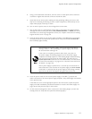
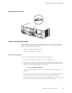
8. Using a 3-mm flat-blade screwdriver, turn the screw on each quick-connect terminal
clockwise to tighten the terminal connector around the cable.
9. Verify that the DC source power cabling and the grounding cabling are correct, that
they are not to
uching or blocking access to router components, and that they do not
drape where people could trip on them.
10. Tu rn on the DC power source so that voltage flows to the router.
11. Turn on the power to a management device that is connected to the Routing Engine
(through the craft interface port labeled AUX/MODEM,CONSOLE,orMGMT). For more
informatio
n on connecting management devices, see “Replace Connectors to Routing
Engine Interface Ports” on page 118.
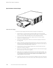
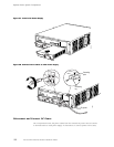
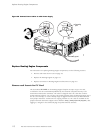
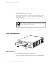
12. Press the power switch on one power supply faceplate to the ON position and engage
the safety interlock lever below the power switch. Verify that the blue OUTPUT OK
LED eventu
ally lights steadily.
After powering off a power supply, wait at least 60 seconds before
turning it back on. After powering on a power supply, wait at least
60 seconds before turning it off.
If the router is completely powered down when you power on
the power supply, t he Routing Engine boots as the power supply
completes its startup sequence. If the Routing Engine finishes bo ot ing
and you need to power down the router again, first issue the CLI
request system halt command. For more information, see “Disconnect
ACPowerfromtheRouter”onpage102or“DisconnectDCPowerfrom
the Router” on page 109.
After a power supply is powered on, it can take up to 60 seconds for
status in
dicators—such as LEDs on the power supply and show chassis
commands—to indicate that the p ower supp ly is functioning normally.
Ignore er
ror indicators that appear during the first 60 seconds.
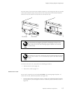
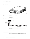
13. Press the power switch for the second power supply to the ON ( | )positionand
observe the LEDs on the second power supply faceplate. They should light as described
in the previous s
tep.
If the LEDs are no
t lit in the appropriate pattern after 60 seconds, repeat the power
supply and cable installation procedures described in “Install a DC Power Supply” on
page 10 6 and the previous steps in this section.
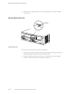
14. On the external management device connected to the Routing Engine, monitor the
startup proces
s to verify that the system has booted properly.
Replace Hardware Components
111