


Replace Power Sys
tem Components
6. Arrange the cable in the cable management system to prevent the cable from dislodging
or developing stress points. Secure the cable so that it is not supporting its own weight
as it hangs to t
he floor. Place excess cable out of the way in a neatly coiled loop in the
cable management system. Placing fasteners on the loop helps to maintain its shape.
Do not let fiber-optic cable hang free from the connector. Do not
allow fastened loops of cable to dangle, which stresses the cable at
the fastening point.
Avoid bending fiber-optic cable beyond its minimum bend radius. An
arc smaller than a few inches in diameter can damage the cable and
cause problems that are difficult to diagnose.
7. Verify that the status LEDs on the PIC faceplate indicate that the SFP is functioning
correctly (there is an LED for each SFP port). For more information about the PIC LEDs,
see the M5 and M10
Internet Routers PIC Guide. You can also verify PIC functioning
by issuing the show chassis fpc pic-status command described in “Maintain PICs
and PIC Cables” on page 76.
Replace Power System Components
For instructio
ns on replacing power system components, see the following sections:
• Replace an AC Power Supply on page 98
• Disconnect and Connect AC Power on page 101
• Replace an AC Power Cord on page 103
• Replace a DC Power Supply on page 104
• Disconnect and Connect DC Power on page 108
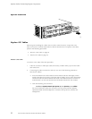
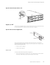
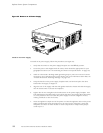
Replace an AC Power Supply
An AC-powered router has two load-sharing, redundant AC power supplies. Each power
supply is hot-removable and hot-insertable, as described in “Field-Replaceable Units (FRUs)”
on page 3. When one power supply fails or is powered down, the other power supply
automatically assumes the entire electrical load for the router. For more information about
AC power supplies, see “ AC Power Supply” on p age 17.
98 M5 and M10 Internet Routers Hardware Guide