


Provide Power to t
he Router
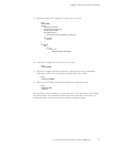
8. Insert the exposed end of each power cable straight into the appropriate quick-connect
terminal:
• Insert the positive (+) source cable into the return terminal, which is labeled RTN.
• Insert the negative (–) source cable into the input terminal, which is labeled –48V.
9. Usinga3-mmfl
at-blade screwdriver, turn the screw on each quick-connect terminal
clockwise to tighten the terminal connector around the cable.
10. Verify that the DC source power cabling and the grounding cabling are correct, that
they are not touching or blocking access to router components, and that they do not
drape where p
eople could trip on them.
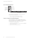
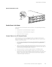
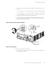
Figure 25: Connect DC Power and Grounding Cables
1331
RTN
-48V
Grounding
point
Grounding
lug
To ground
Power On the Router
To power on the router, follow this procedure:
1. Verify that the power supplies are fully in serted in the chassis and the thumbscrews on
their faceplates are tightened.
Connect the Router and Perform Initial Configuration
67