


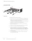
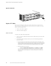

Replace Packet Fo
rwarding Engine Components
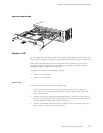
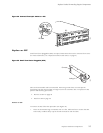
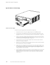
3. Insert the cable connector into the cable connector port on the PIC faceplate.
4. Arrange the cable in the cable management system to prevent it from dislodging or
developing stress points. Secure the cable so that it is not supporting its own weight as
it hangs to the
floor. Place excess cable out of the way in a neatly coiled loop in the
cable management system. Placing fasteners on the loop helps to maintain its shape.
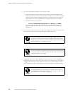
Avoid bending fiber-optic cable beyond its minimum bend radius. An
arc smaller than a few inches in diameter can damage the cable and
cause problems that are difficult to diagnose.
Do not let fiber-optic cable hang free from the connector. Do not
allow fastened loops of cable to dangle, which stresses the cable at
the fastening point.
5. Insert the other end of the cable into the destination port.
6. Repeat the previous steps for any additional cables.
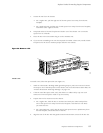
7. If the PIC is offline (its failure indicator LED is lit), use one of the following meth od s to
bring the PIC online:
• Press and hold the PIC offline button until the s tatus LED on the PIC faceplate
indicates norm
al functioning, which usually takes about 5 seconds. The LED is
usually green; for more information, see the M5 and M10 Internet Routers PIC Guide.
The offline button for each PIC is located below it on the craft interface and
is labeled wit
hthePICslotnumber.
• IssuethefollowingCLIcommand:
user@host>request chassis pic fpc-slot fpc-slot pic-slot pic-slot online
For more infor
mation about th e command, see the JUN OS Internet Software
Operational Mode Command Reference: Protocols, Class of Service, Chassis, and
Management.
The normal functioning indicator LED confirms that the PIC is online. You can also
verify correct PIC functioning by issuing the show chassis fpc pic-status command
described in “
Maintain P ICs and PIC Cables” on page 76.
94 M5 and M10 Internet Routers Hardware Guide