


KS152JB Universal Communications Controller
Technical Specifications
Kawasaki LSI USA, Inc. Page 109 of 120 Ver. 0.9 KS152JB2
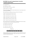
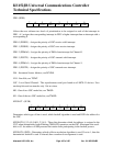
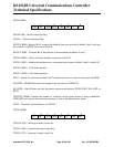
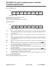
SCON (098H)
SCON.0 (RI) - Receive Interrupt Flag.
SCON.1 - Transmit Interrupt Flag.
SCON.2 (RB8) - Receive Bit 8, contains the ninth bit that was received in Modes 2 and 3 and stop
bit in Mode 1 if SM20. Not used in Mode 0.
SCON.3 (TB8) - Transmit Bit 8, the ninth bit to be transmitted in Modes 2 and 3.
SCON.4 (REN) - Receive Enable, enables reception for the LSC.
SCON.5 (SM2) - Enables the multiprocessor communication feature in Modes 2 and 3 for the LSC.
SCON.6 (SM1) - LSC mode specifier.
SCON.7 (SM2) - LSC mode specifier.
SDLC - Stands for synchronous Data Link Communication and is a protocol developed by IBM.
SLOTTM - (0B4H) Determines the length of the slot time in CSMA/CD.
SP (081H) - Stack Pointer, an eight bit pointer register used during a PUSH, POP, CALL, RET or
RETI.
TCDCNT (0D4H) Contains the number of collisions in the current frame if using probabilistic
CSMA/CD and contains the maximum number of slots in the deterministic mode.
TCDT - Transmit Collision Detect, see TSTAT.
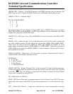
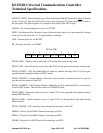
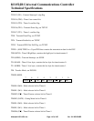
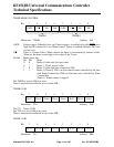
TCON (088H)
TCON.0 (IT0) - Interrupt 0 mode control bit.
TCON.1 (IE0) - External interrupt 0 edge flag.
TCON.2 (IT1) - Interrupt 1 mode control bit.
01234567
REN TB8 RB8 TI RISM2SM1SM0
01234567
TR0 IE1 IT1 IE0 IT0TF0TR1TF1