


KS152JB Universal Communications Controller
Technical Specifications
Kawasaki LSI USA, Inc. Page 14 of 120 Ver. 0.9 KS152JB2
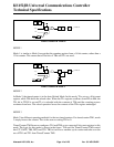
MODE 1
Mode 1 is similar to Mode 0 except that the counting register form a 16 bit counter, rather than a
13 bit counter. This means that all the bits of THx and TLx are used.
.
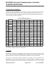
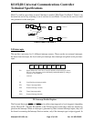
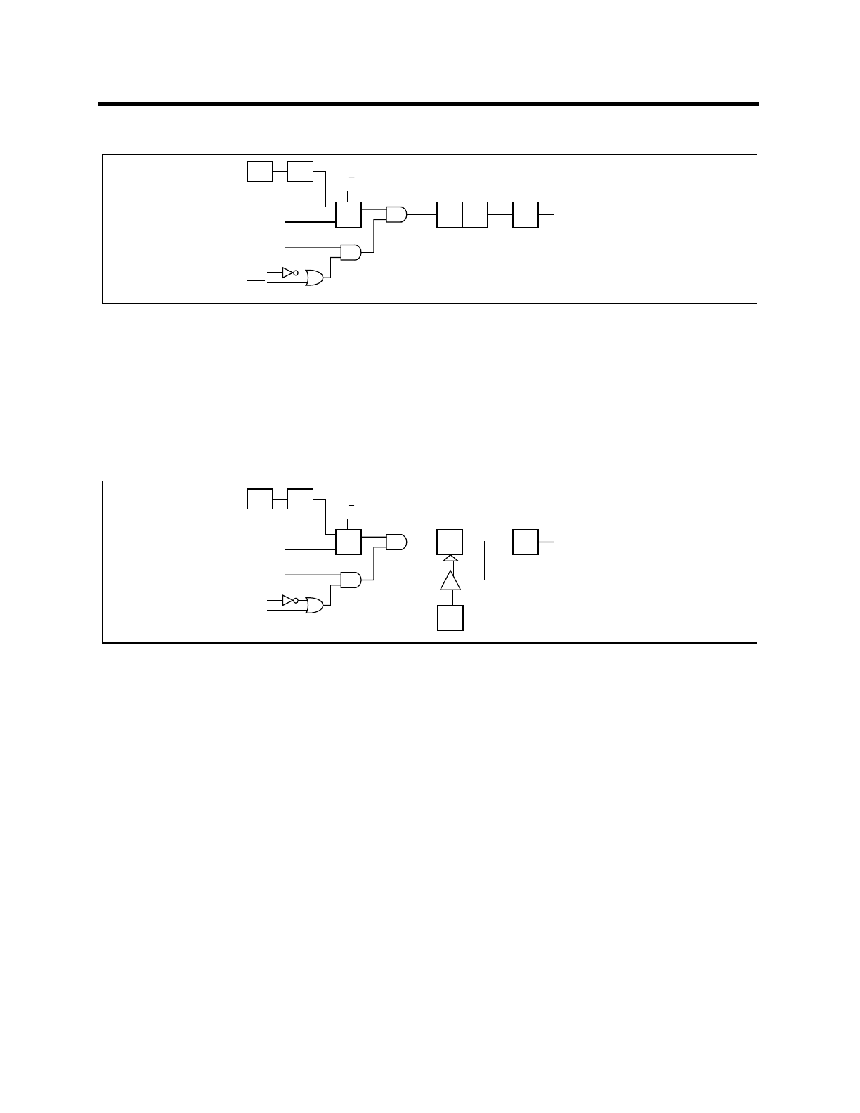
MODE 2
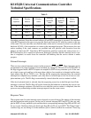
In Mode 2, the timer/counter is in the Auto Reload Mode. In this mode, TLx acts as a 8 bit count
register, while THx holds the reload value. When the TLx register overflows from FFh to 00h, the
TFx bit in TCON is set and TLx is reloaded with the contents of THx and the counting process
continues from here. The reload operation leaves the contents of the THx register unchanged
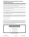
MODE 3
Mode 3 has different operating methods for the two timer/counters. For timer/counter TM1, mode
3 simply freezes the counter. This is the same as setting TR1 to 0.
Timer/Counter TM0 however configures TL0 and TH0 as two separate 8 bit count registers in this
mode. The logic for this mode is shown in the figure. TL0 uses the Timer/Counter TM0 control
bits C/T, GATE, TR0, INT0 and TF0. TH0 is forced as a machine cycle counter and takes over the
use of TR1 and TF1 from Timer/Counter TM1.
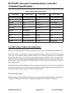
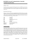
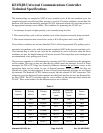
S3P1OSC
I0
I1
Q
GATE
INTx
pin
TRx
Tx pin
TLX
5 bits
THx
8 bits
TFx
INTERRUPT
C/T
Timer/Counter in Mode 0
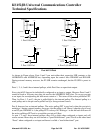
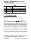
S3P1OSC
I0
I1
Q
GATE
INTx
pin
TRx
Tx pin
TLX
8 bits
THx
8 bits
TFx
INTERRUPT
C/T
Timer/Counter in Mode 2
Reload