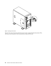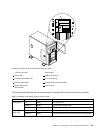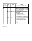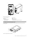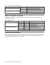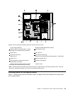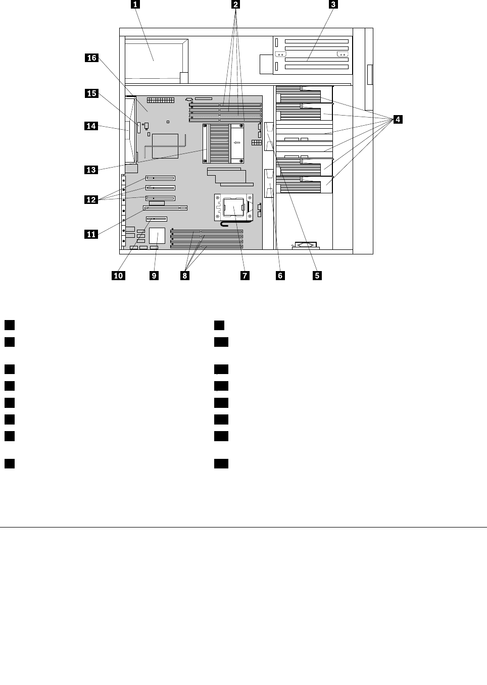
Figure 6. Server component locations (side view without the server cover)
1 Power supply assembly
9 Onboard ICH10R SATA RAID controller
2 Memory slots for microprocessor 1 (some
slots might with installed memory modules)
10 PCI Express x4 slot
3 Optical drive 11 PCI card slot
4 Hard disk drive zone*
12 PCI Express x8 slots (3)
5 System fan 2 13 Heat sink and fan assembly (microprocessor 1 underneath)
6 System fan 1 14 Rear fan (system fan 3)
7 Microprocessor 2 socket (the second
microprocessor is optional)
15 System board battery
8 Memory slots for microprocessor 2 (some
slots might with installed memory modules)
16 System board
Note: * denotes that this illustration only shows the server models with four hot-swap hard disk drives. There are
also server models that support up to ve non-hot-swap hard disk drives.
Locating parts on the system board
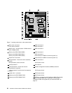
Figure 7 “Locating major parts on the system board” on page 34 shows the locations of the major parts
on the system board.
Chapter 4. Locating parts, controls, LEDs, and connectors 33


