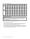
Table 6. Memory module installation rules
CPU DIMM
CPU1
DIMM
CHA2
CPU1
DIMM
CHA1
CPU1
DIMM
CHB2
CPU1
DIMM
CHB1
CPU2
DIMM
CHD2
CPU2
DIMM
CHD1
CPU2
DIMM
CHE2
CPU2
DIMM
CHE1
One
DIMM
X
Two
DIMMs*
X, 1 X, 2
CPU 1
Four
DIMMs
X, 3 X, 1 X, 4 X, 2
Two
DIMMs
X, 1 X, 2
Four
DIMMs*
X, 1 X, 3 X, 2 X, 4
Six
DIMMs
X, 5 X, 1 X, 3 X, 6 X, 2 X, 4
CPU 1
and CPU
2
Eight
DIMMs
X, 5 X, 1 X, 7 X, 3 X, 6 X, 2 X, 8 X, 4
Note: * denotes the Channel Mirroring Mode. This mode requires that you install the DIMMs in pair.
Installing a memory module
Attention:
Do not open your server or attempt any repair before reading and understanding the Safety Information and the
Warranty and Support Information on the ThinkServer Documentation DVD that came with your product, and
“Guidelines” on page 39
. To obtain a copy of the publications, go to:
http://www.lenovo.com/support
This section provides instructions on how to install a memory module.
To install a memory module, do the following:
1. Remove all media from the drives and turn off all attached devices and the server. Then, disconnect all
power cords from electrical outlets and disconnect all cables that are connected to the server.
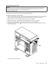
2. Remove the server cover. See “Removing the server cover” on page 43.
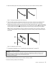
3. Locate the appropriate memory slot on the system board into which you will install the memory module.
To optimize system performance, follow the related memory module installation rules and install the
memory module into a memory slot starting with the memory module farthest from the microprocessor.
See “Memory module installation rules” on page 49
.
50 ThinkServer TD230 Hardware Maintenance Manual


