1
2
3
1
2
3
1
2
3
1
2
3
1
2
3
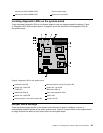
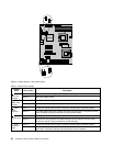
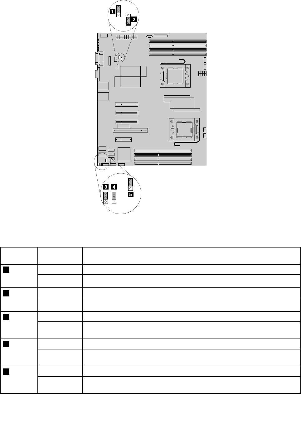
Figure 9. Jumper blocks on the system board
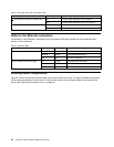
Table 5. Jumper block settings
Jumper
block Pin position Description
Pins 1-2
These pins should have a jumper in place for normal system operation (default).
1 J8B5:
ME Force
Update
Pins 2-3
ME force update model.
Pins 1-2
BMC Firmware Force Update Mode – Disabled (default)2 J8C1:
BMC force
update
Pins 2-3
BMC Firmware Force Update Mode – Enabled
Pins 1-2
These pins should have a jumper in place for normal system operation (default).
3 J1A1:
BIOS
recovery
Pins 2-3
The main system BIOS will not boot with these pins jumpered. The system will boot
from a bootable recovery media with a recovery BIOS image.
Pins 1-2
These pins should have a jumper in place for normal system operation (default).
4 J2D2:
CMOS clear
Pins 2-3
If these pins are jumpered, the CMOS settings will be cleared on the next reset.
These pins should not be jumpered for normal operation.
Pins 1-2
These pins should have a jumper in place for normal system operation (default).
5 J2D1:
Password
clear
Pins 2-3
If these pins are jumpered, administrator and user passwords will be cleared on the
next reset. These pins should not be jumpered for normal operation.
36 ThinkServer TD230 Hardware Maintenance Manual


