


CALIBRATION AND TROUBLESHOOTING
Recommended Equipment
90 LDX-3232
CHAPTER 6
Finally, the LDX-3232 Current Source should be allowed to warm up for at least
one hour before calibration.
Recommended Equipment
Recommended test equipment for calibrating the LDX-3232 Current Source is
listed in Table 6.1. Equipment other than that shown in the table may be used if
the specifications meet or exceed those listed.
Table 6.1 Recommended Test Equipment
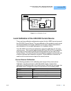
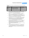
It will be necessary to connect various loads and circuits to the outputs of each
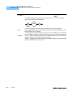
current source for the calibration procedure. A schematic is shown in Figure 6.1
for the photodiode calibration circuit with the required components listed in Table
6.2. Also, the devices required for other calibration loads are listed in Table 6.2.
Table 6.2 Required Calibration Components
Description Manufacturer/Model Specification
DMM HP 3457A DC Amps (@ 1.0 A): ±0.02%
Resistance (@ 10 Ω): ±0.02%
0.1 µA or 0.1 mV resolution
Laser Current Source Calibration
Current Source Calibration, all models 10 Ω, 20 W resistor, low TCR
Voltage Measurement Calibration 15 Ω, 5 W resistor, low TCR
PD Monitor Calibration (See Schematic in Figure 6.1)
PD Calibration Circuit
R1
R2
R4
R3
U1
49 Ω resistor, 1%, 1/4 W
100 Ω resistor, 1%, 1/4 W
1.0 MΩ resistor, 1%, 1/4 W
5 Ω, 1%, 10W
TIL 117 opto isolator