


REMOTE OPERATION
Command Timing and Completion
32 LDX-3232
CHAPTER 3
Command Timing and Completion
This section describes, for each device-dependent command, whether that
command is performed in an overlapped or sequential manner. In other words, it
states whether the next command may begin while the current command is being
executed, or if the next command must wait until the current command is
completed before its execution begins. The conditions for setting the operation
complete flag are given in the Chapter 3 section titled Operation Complete
Definition.
All LDX-3232 device-dependent commands are executed in an overlapped
manner, except the DELAY command that is sequential. The operation complete
flag is set after the conditions outlined in the Operation Complete Definition have
been satisfied.
The *WAI (common command) is an example of a sequential command that
forces the next command to wait until the no-operation-pending flag is true. This is
essentially the same as waiting for the OPC flag to become true, because the no-
operations-pending flag is used to set the OPC flag (bit 0 of the Standard Event
Status Register).
Commands that change the status of the instrument limits or change its mode or
current range, step value, or status enable registers will not have their OPC flag
set until all current writing to non-volatile memory has been completed. This is
done to ensure that the OPC flag is never set prematurely.
Whenever there is any output (response) data in the Output Queue, bit 4 is set in
the Status Byte Register. Whenever there is any error message in the Error
Queue, bit 7 is set in the Status Byte Register.
Error Messages
In the event of a hardware error condition, error messages will be displayed on the
display. In most cases, the error message will appear for three seconds. In some
cases the error code display will remain until the user changes display modes. In
the case of multiple error messages, the display may sequentially show each
message for three seconds. In addition to the hardware errors, GPIB errors may
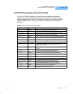
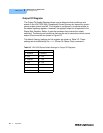
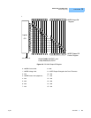
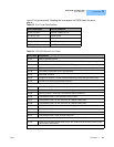
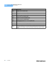
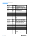
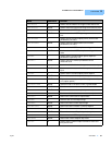
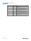
be read via the ERR? query. Table 3.4 lists the numerical error ranges by function.
Table 3.5 contains all of the error messages that may be generated. Not all of
these messages may appear on the front panel displays. Some refer to GPIB
activities only.
In remote operation, the errors can be read by issuing the ERR? query. When this
is done, all of the error messages that are resident in the error queue are returned