


OPERATION
Connecting to the Laser
04_06 LDX-3232 13
CHAPTER 2
Photodiode Connections
Many laser diode modules contain an internal photodiode that monitors the back-
facet emission of the laser. Usually, this photodiode is internally connected to
either the laser anode or cathode.
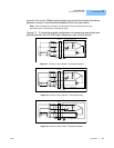
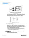
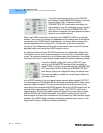
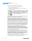
The photodiode and laser connections to the LDX-3232 are electrically isolated
from ground and each other. So, if a 4 pin connection is made (no common
connections), no additional jumpers are required. Figures 2.1 - 2.4 show the
recommended connections and shielding for 3-pin lasers (where the common
connection is internal to the device). A 4-pin laser should be connected with the
same shielding as shown in Figure 2.1, but the common connection (between the
photodiode and the laser) is optional.
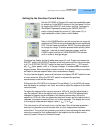
Setting the PD Bias
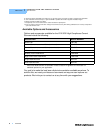
The LDX-3232 provides an adjustable reverse bias of 0-5 VDC for the photodiode.
To set the photodiode bias to 5 V reverse bias, turn the back panel PD BIAS
ADJUST fully clockwise. To set the photodiode bias to 0 V reverse bias, turn the
back panel PD BIAS ADJUST fully counter-clockwise.
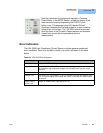
Grounding Considerations
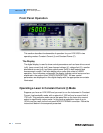
The LASER outputs of the LDX-3232 High Compliance Current Source are
isolated from chassis ground, allowing either output terminal to be grounded at the
user's option. Figures 2.1 - 2.4 show the proper earth-ground shielding for laser
diode/photodiode connections.