


OPERATION
Connecting to the Laser
10 LDX-3232
CHAPTER 2
The Power On State
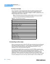
You can choose to "clear" the last saved state by recalling the default values.
These values are stored in BINS to that you can save or recall instrument
configurations (described in more detail in Chapter 5). "BIN 0" contains all of the
default configurations listed in Table 2.1.
Note: If the instrument cannot successfully complete the power on test, an error message
of E-512 or E-513 will be displayed on the Display. See Chapter 3 for a list of error codes
and actions to take when your instrument indicates these errors.
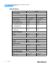
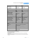
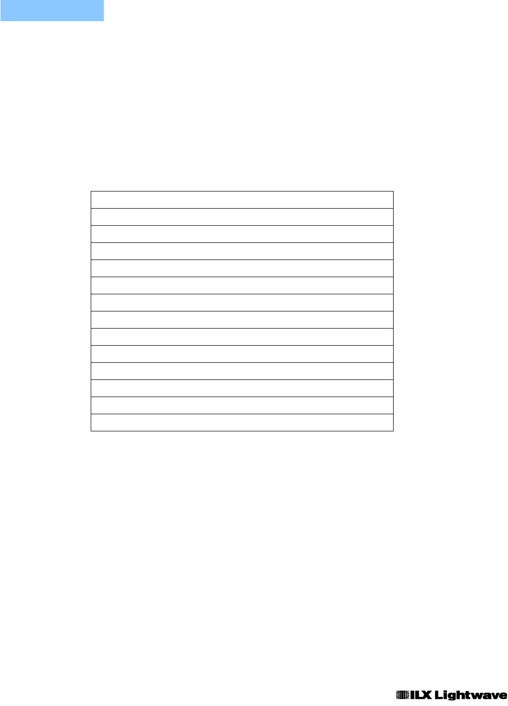
Table 2.1 LDX-3232 Default Settings
Connecting to the Laser
When connecting your laser to the LDX-3232, we recommend that the instrument
be powered up with the output off. In this condition, a low impedance shunt is
active across the output terminals. When disconnecting devices, it is only
necessary to turn the current source output off.
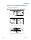
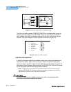
It is also recommended that the connections to the LDX-3232 output be made
using twisted wire pairs with an earth-grounded shield (see Figures 2.1 - 2.4). The
output terminals of the instrument are left floating relative to earth ground to
suppress AC power-on/power-off transients that may occur through an earth-
ground path. If the output circuit is earth-grounded at some point (such as through
the laser package and mount), the user must be careful to avoid multiple earth
GPIB mode in LOCAL via front panel, or in REMOTE via GPIB
PARAMETERS not selected
CAL PD = 0 µA / mW
LIM I (high range) = 1000 mA
LIM I (low range) = 500 mA
LIM V = 15 volts
LIM P = 5000 mW
Output off
DISPLAY enabled, in I mode
Constant I, low bandwidth mode selected
I setpoint = 0 mA
I
PD
setpoint = 0 µA
P
PD
setpoint = 0 mW
RECALL BIN number = 0