


15
CONNECTIONS
PRINTING
ADJUSTMENTS
PRECAUTIONS FEATURES
PREPARATION
OTHERS
TROUBLE-
SHOOTING
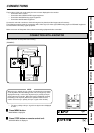
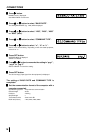
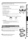
RS-232 Connection Cable
Computer (DB9) Printer (DB25)
Signal Pin No. Pin No. Signal
RXD 2 2 TXD
TXD 3 3 RXD
DR 4 6 DSR
SG 5 7 GND
DR 6 20 DTR
RS 7 5 CTS
CS 8 4 RTS
FG 9 1 FG
• #9 on the 9 Pin end of the cable is typically tied to the Shield.
• This is just an example. Make sure to check the connection type
for the using equipment.
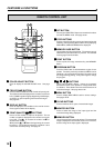
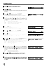
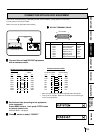
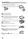
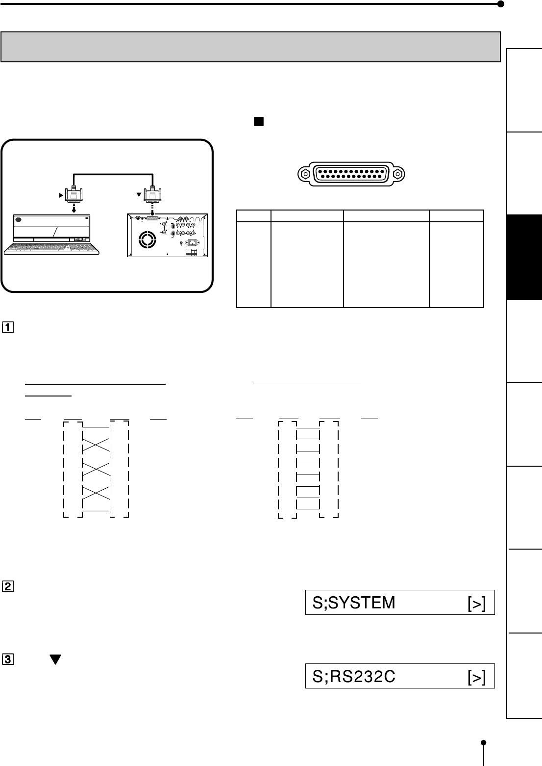
CONNECTION WITH RS-232C EQUIPMENT
This unit can controlled through a RS-232C port with custom software. (Image data can not be input.)
For the protocol, consult your dealer.
Make sure to turn off the power before setting.
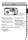
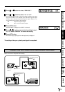
RS-232C TERMINAL SIGNAL
REMOTE
RS-232C
S-VIDEO IN
S-VIDEO OUT
R
G/G+SYNC B Y/SYNC
IN
VIDEO
75Ω
75Ω/HIGH
AC LINE
OUT
75Ω/HIGH
75Ω
75Ω
75Ω
75Ω
HIGH
HIGH
HIGH
HIGH
ON
OFF
POWER
HIGH
IMPEDANCE
RGB
75Ω
75Ω/HIGH
HIGH
SYNC
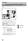
To RS-232C terminal
(RS-232C)
To RS-232C treminal
VCP
Equipment with RS-232C
25
14
13
Pin number
1
Pin No. Signal line name Description Directions
1 FG Protective ---
2 TXD Transmitted data Output
3 RXD Received data Input
4 RTS Request to send Output
5 CTS Clear to send Input
6 DSR Data set ready Input
7 GND Signal ground ---
20 DTR Data terminal ready Output
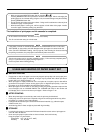
RS-232 Connection Cable (Cross-
over cable)
(DB25) (DB25)
Signal Pin No. Pin No. Signal
FG 1 1 FG
TXD 2 2 TXD
RXD 3 3 RXD
RTS 4 4 RTS
CTS 5 5 CTS
DSR 6 6 DSR
DTR 20 20 DTR
GND 7 7 GND
Connect this unit and RS-232C equipment
with a crossover cable.
Set the baud rate according to the equipment
to be connected.
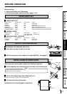
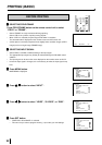
Press MENU button, then press STOP button
on remote control unit.
SERVICE MENU is displayed.
Press button to select “RS232C.”