


32
Pin No.
22kΩ
22kΩ
10kΩ
100Ω
DTC124EK
DC5V
1kΩ
74LVC125
10kΩ
100Ω
DC5V
To VCP
To VCP
From VCP
To VCP
Circuit inside the VCP
MEMORY
BUSY2
PRINT
REMOTE
BUSY1
74LVC125
10kΩ
100Ω
DC5V
TTL level
TTL level
56kΩ
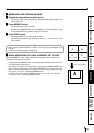
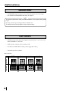
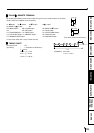
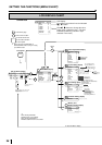
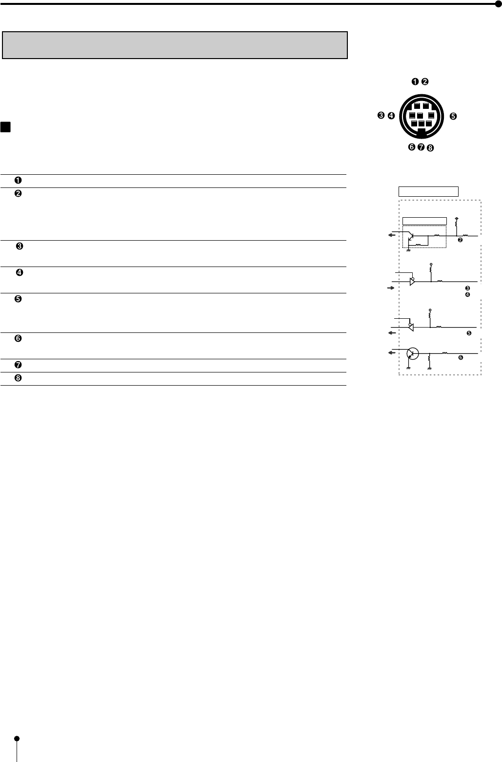
EXTERNAL REMOTE TERMINAL 2
The image can be stored in memory and printed by sending the remote signal through
the external remote terminal on the rear panel.
• Make out the necessary circuit to use this function by referring to the following.
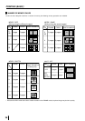
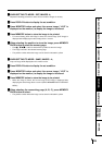
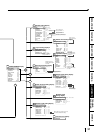
EXTERNAL REMOTE TERMINAL SIGNAL ALLOCATION (MINI
DIN8PIN)
Pin No. Function Description
Ground Earth
MEMORY Memory : When the signal becomes “LOW” from “HIGH”, the
image is stored in memory. (When the signal has
been “LOW” for 15ms or more, the image is stored
in memory. See page 51, 52.)
BUSY2 Refer to the BUSY LEVEL setting of REMOTE SET in
SERVICE MENU. See page 52.
BUSY1 Refer to the BUSY LEVEL setting of REMOTE SET in
SERVICE MENU. See page 52.
PRINT When the signal becomes “LOW” from “HIGH”, the image is
stored in memory. (When the signal has been “LOW” for 15ms
or more, the image is stored in memory.)
REMOTE The same functions as the supplied remote control can be
controlled.
Unused
DC3V Power supply for the remote control DC 1mA Max.
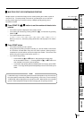
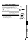
• When the signal from BUSY terminal is received with TTL level, keep the following.
| I
OL
| = 2mA or less, | I
OH
| = 1mA or less
| I
OL
| means the current flowing into the unit at Low output, | I
OH
| means the
current flowing out of the unit at High output.
• Just after completing printing, there is a period that memory signal is not accepted.
PRINTING (SPECIAL)