


9
CONNECTIONS
PRINTING
ADJUSTMENTS
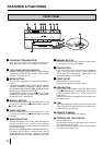
FEATURES
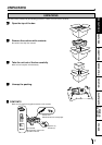
PREPARATION
OTHERS
TROUBLE-
SHOOTING
PRECAUTIONS
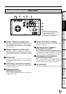
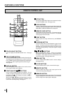
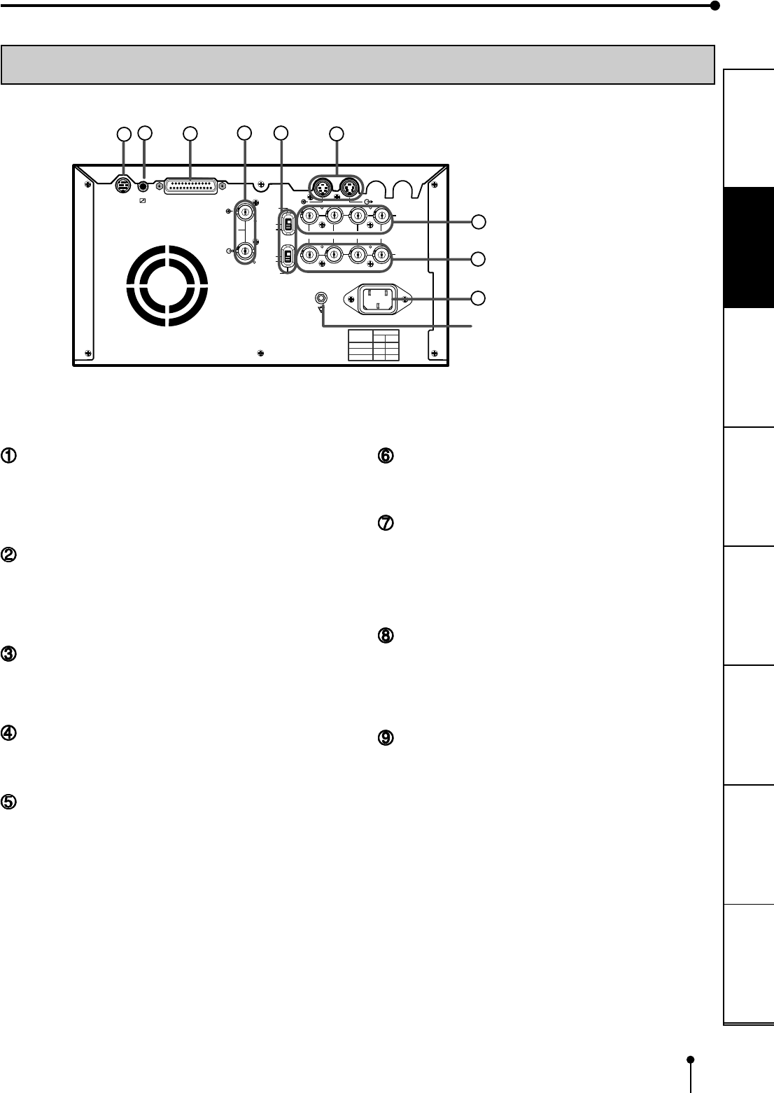
REAR PANEL
REMOTE TERMINAL 2 (MINI DIN 8 PIN)
Memorizing images and printing is available by the remote
signal inputted through this terminal. It is necessary to
make a circuit for remote control unit to use the function.
See pages 32-33.
REMOTE TERMINAL 1 (STEREO JACK)
Memorizing images is available by the remote signal
inputted through this terminal. It is necessary to make a
circuit for remote control unit to use the function. See page
31.
RS-232C PORT
Use these terminals to connect this unit to a device
equipped with RS-232C interface. See pages 15-16 for
connection.
VIDEO SIGNAL INPUT/OUTPUT TERMINAL
Use these terminals to connect this unit to VIDEO signal
equipment. See pages 13.
IMPEDANCE SWITCH
[IMPEDANCE RGB SYNC.]
This is a 75ΩHIGH/75Ω/HIGH impedance selection switch
for RGB or Sync. signal.
S-VIDEO INPUT/OUTPUT TERMINAL
Use these terminals to connect to S-VIDEO signal
equipment. See pages 13.
RGB ANALOG INPUT TERMINALS
[R G/G+SYNC B H+V-SYNC]
This is a BNC type input terminal for a RGB analog signal.
The sync. signal can be automatically selected between
H/V composite and SYNC. ON GREEN (sync. signal
imposed on the green video signal) signals. See page 14.
RGB ANALOG OUTPUT TERMINALS
[R G/G+SYNC B H+V-SYNC]
This is a monitor output terminal for a RGB analog signal.
The sync. signal can be selected between 0.3V (H+V-
SYNC) and TTL (H+V-SYNC) signals. See page 14.
AC LINE SOCKET
Connects to the provided power cord. Insert the cord firmly.
REMOTE
RS-232C
S-VIDEO IN
S-VIDEO OUT
R
G/G+SYNC B Y/SYNC
IN
VIDEO
75Ω
75Ω/HIGH
AC LINE
OUT
75Ω/HIGH
75Ω
75Ω
75Ω
75Ω
HIGH
HIGH
HIGH
HIGH
ON
OFF
POWER
HIGH
IMPEDANCE
RGB
75Ω
75Ω/HIGH
HIGH
SYNC
1
2
3
4
6
7
8
9
5
Potential equalization connector
This is used to equalize the potential of the
equipment connected to the unit.
For details, refer to the installation instruction
of the equipment to be connected.