


D
D
Appendix D. DIO Commands
In this appendix, we provide information on sending commands to the module’s DIO channels
over an Ethernet network. Digital I/O commands and responses are accessed using a specific TCP
port (default 5001) on the module. Each command is initiated by the host and is followed by a
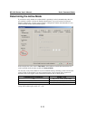
response from the module. A utility on the CD-ROM can be used to test the DIO access
commands.
Overview
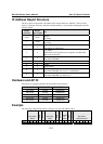
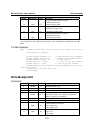
Each DIO command and response consists of a 4-byte header and up to 255 bytes of data. The first
byte of the header indicates the command. The second byte indicates the version, which is “2” for
current firmware versions. The third byte is a code that is used by the module to report errors. The
fourth byte is the number of bytes that follows the header, and will depend on the command or
response.
In the event of an error, the module will return the entire command as its response, but with the
third byte changed according to the following status/error codes:
1: Command error; may be unknown
2: Version error; not supported by this version
3: Length error; the length member does not match the attached data
4: Operation error; invalid status or invalid mode
5: “Packet too short” error
6: DIO number error; might not support request DIO number
0xFF: other unknown error
ATTENTION
DIO command data is transmitted as values rather than text strings. A value of 1 would be
transmitted as 0x01.
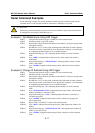
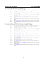
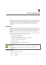
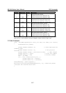
C Code Example
//define DIO Header format
typedef struct _DIO_Header_Struct {
char command;
char version; /* This specification is version 2 */
char status;
char length;