


NE-4100 Series User’s Manual Panel Layout and Pin Assignments
2-10
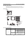
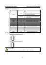
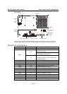
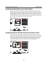
NE-4120-ST
1234
ON
DIP
910
13 14
12
12
Jumper 9 (J9)Jumper 7 (J7)
Jumper 10
(J10)
Power
Jack
Ethernet
Port
Serial Port (RS-232)Debug Serial COM Port DI/O Terminal Block
Reset Button
DI/O Signal
Setting
Switches
DI/O Selector
Jumpers
Interface
Selector
Jumpers
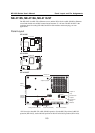
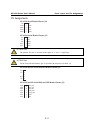
149.00 mm
99.00 mm
5
3
3
2
1
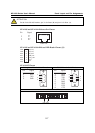
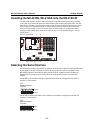
* JP2 is used to select RS-232 or RS-422/485 operation. Use the RS-232 position for RS-232
operation (NE-4120S); use the RS-485 position for RS-422 or RS-485 operation (NE-4120A).
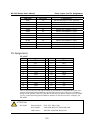
NE-4120-ST LED Indicators
LED Name LED Color LED Function
Power red Indicates the power is on.
Steady on: Power is on and NE-4120 is
functioning normally.
green
Blinking: NE-4120 has been located by
Network Enabler Administrator.
Ready
off
y Power is off, or power error condition exists.
y IP address cannot be found in DHCP mode.
y IP address conflict.
DIO0 red Indicates that DIO is in “low” (0) status.
DIO1 red Indicates that DIO is in “low” (0) status.
DIO2 red Indicates that DIO is in “low” (0) status.
DIO3 red Indicates that DIO is in “low” (0) status.
TXD0 red Indicates that TXD0 has a signal.
RXD0 red Indicates that RXD0 has a signal.
DTR0 red Indicates that DTR0 has a signal.
CTS0 red Indicates that CTS0 has a signal.
DSR0 red Indicates that DSR0 has a signal.
DCD0 red Indicates that DCD0 has a signal.
RTS0 red Indicates that RTS0 has a signal.
TXD1 red Indicates that TXD1 has a signal.
RXD1 red Indicates that RXD1 has a signal.