


NE-4100 Series User’s Manual DIO Commands
D-7
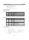
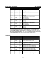
Byte # Descriptor Value Description
8 Data
0, 1
2nd requested DIO channel
0: channel status has been changed to low
1: channel status has been changed to high
9 Data 0, 1
3rd requested DIO channel, optional
0: channel has been changed to input mode
1: channel has been changed to output mode
10 Data 0, 1
3rd requested DIO channel, optional
0: channel status has been changed to low
1: channel status has been changed to high
11 Data 0, 1
4th requested DIO channel, optional
0: channel has been changed to input mode
1: channel has been changed to output mode
12 Data 0, 1
4th requested DIO channel, optional
0: channel status has been changed to low
1: channel status has been changed to high
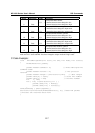
For example, the 8-byte response 6-2-0-4-0-0-1-1 indicates that DIO 0 has been changed to input
mode and “low” status and DIO 1 has been changed to output mode and “high” status.
C Code Example:
void WriteMultipleDIO(int start, int end, int* mode, int* status)
{
DIOPacketStruct packet;
packet.header.command = 6; // Write Multiple DIO
Command Codes
packet.header.version = 2; // DIO protocol
version
packet.header.length = (end-start+1)*2+2; // data length
packet.data[0] = start; // start DIO number
packet.data[1] = end; // end DIO number
int i, len;
for ( i=0; i<(end-start+1);i++ ) {
packet.data[i+2] = mode[i];
packet.data[i+3] = status[i];
}
send(SocketFd, )(char*)&packet,(
end-start+1)*2+2+sizeof(DIOHeaderStruct), 0); //Send TCP packet
//Process the returned data here
}