


NE-4100 Series User’s Manual DIO Commands
D-3
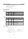
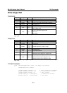
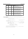
Write Single DIO
Command
Byte # Descriptor Value Description
1 Header 2 command number, fixed
2 Header 2 version, fixed
3 Header (any) this byte is only used in the module’s response
4 Header 3 data length, fixed
5 Data 0,1,2,3 desired DIO channel number
6 Data 0, 1
0: set to input mode
1: set to output mode
7 Data 0, 1
this byte is ignored for input mode
0: set to low
1: set to high
For example, the 7-byte command sequence 2-2-0-3-0-0-0 requests that DIO 0 be set to digital
input mode.
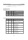
Response
Byte # Descriptor Value Description
1 Header 2 command number, fixed
2 Header 2 version, fixed
3 Header
0, 1, 2, 3,
4, 5, 6,
0xFF
command status/error code (0 = okay)
4 Header 3 data length, fixed
5 Data 0, 1, 2, 3 desired DIO channel #
6 Data 0, 1
0: channel has been changed to input mode
1: channel has been changed to output mode
7 Data 0, 1
this byte is ignored for input mode
0: channel status has been changed to low
1: channel status has been changed to high
For example, the 7-byte response sequence 2-2-0-3-0-0-0 indicates that DIO 0 has been changed to
input mode.
C Code Example:
void WriteSingleDIO(int port, int mode, int status)
{
DIOPacketStruct packet;
packet.header.command = 2; // write single DIO command
packet.header.version = 2; // DIO protocol version
packet.header.length = 3; // data length
packet.data[0] = (char)port; // number of the DIO
packet.data[1] = (char)mode; // DIO mode