


NE-4100 Series User’s Manual Panel Layout and Pin Assignments
2-6
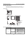
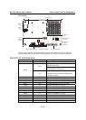
NE-4110-ST LED Indicators
LED Name LED Color LED Function
Power red Indicates the power is on.
Steady on: Power is on and NE-4110 is
functioning normally.
green
Blinking: NE-4110 has been located by
Network Enabler Administrator.
Ready
steady off
y Power is off, or power error condition exists.
y IP address cannot be found in DHCP mode.
y IP address conflict.
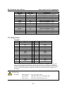
DIO0 red Indicates that DIO is in “low” (0) status.
DIO1 red Indicates that DIO is in “low” (0) status.
DIO2 red Indicates that DIO is in “low” (0) status.
DIO3 red Indicates that DIO is in “low” (0) status.
TXD0 red Indicates that TXD0 has a signal.
RXD0 red Indicates that RXD0 has a signal.
DTR0 red Indicates that DTR0 has a signal.
CTS0 red Indicates that CTS0 has a signal.
DSR0 red Indicates that DSR0 has a signal.
DCD0 red Indicates that DCD0 has a signal.
RTS0 red Indicates that RTS0 has a signal.
TXD1 red Indicates that TXD1 has a signal.
RXD1 red Indicates that RXD1 has a signal.
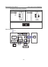
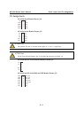
Pin Assignments
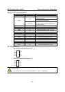
NE-4110S Serial Header Pinouts (J1)
9
7
5
3
1
10
8
6
4
2
NC
RTS0
GND
TxD0
DCD0
NC
CTS0
DSR0
DTR0
RxD0
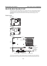
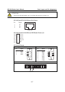
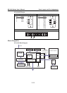
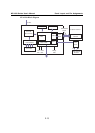
NE-4110A Serial Header Pinouts (J1)
9
7
5
3
1
10
8
6
4
2
NC
GND
NC
NC
NC
RxD-
TxD+
NC
RxD+
TxD-
ATTENTION
The symbols “B” and “A” are often used in place of “+” and “-”, respectively.