


Table of Contents
Chapter 1. Introduction ...............................................................................................1-1
Overview .............................................................................................................................. 1-2
Package Checklist................................................................................................................. 1-2
Product Features................................................................................................................... 1-2
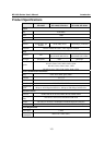
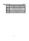
Product Specifications.......................................................................................................... 1-3
Chapter 2. Panel Layout and Pin Assignments ........................................................2-1
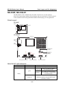
NE-4100T, NE-4100-ST....................................................................................................... 2-2
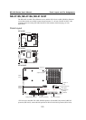
Panel Layout................................................................................................................. 2-2
NE-4100-ST LED Indicators........................................................................................ 2-2
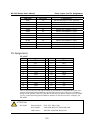
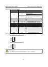
Pin Assignments ........................................................................................................... 2-3
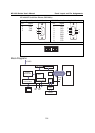
Block Diagrams............................................................................................................ 2-4
NE-4110S, NE-4110A, NE-4110-ST.................................................................................... 2-5
Panel Layout................................................................................................................. 2-5
NE-4110-ST LED Indicators........................................................................................ 2-6
Pin Assignments ........................................................................................................... 2-6
Block Diagrams............................................................................................................ 2-8
NE-4120S, NE-4120A, NE-4120-ST ................................................................................... 2-9
Panel Layout................................................................................................................. 2-9
NE-4120-ST LED Indicators...................................................................................... 2-10
Pin Assignments ......................................................................................................... 2-11
Block Diagrams.......................................................................................................... 2-12
Chapter 3. Getting Started ..........................................................................................3-1
Wiring Precautions ............................................................................................................... 3-2
Installing the NE-4100T onto the NE-4100-ST.................................................................... 3-3
Installing the NE-4110S, NE-4110A onto the NE-4110-ST ................................................. 3-3
Installing the NE-4120S, NE-4120A onto the NE-4120-ST................................................. 3-4
Selecting the Serial Interface................................................................................................ 3-4
Circuit Pad for External Connection..................................................................................... 3-5
Connecting the Power........................................................................................................... 3-5
Connecting to the Network................................................................................................... 3-6
Connecting to a Serial Device .............................................................................................. 3-6
Digital I/O Channel Settings................................................................................................. 3-6
Digital Output LED Circuit Design.............................................................................. 3-8
Chapter 4. Choosing the Proper Operation Mode ....................................................4-1
Overview .............................................................................................................................. 4-2
TCP Server Mode................................................................................................................. 4-2
TCP Client Mode.................................................................................................................. 4-3
UDP Mode............................................................................................................................ 4-3
Real COM Mode .................................................................................................................. 4-4
Chapter 5. Initial IP Address Configuration...............................................................5-1
Static vs. Dynamic IP Address.............................................................................................. 5-2
Factory Default IP Address................................................................................................... 5-2
NE-4100 Series Administration Suite................................................................................... 5-2
ARP ...................................................................................................................................... 5-2
Telnet Console...................................................................................................................... 5-3
Serial Console (19200, n, 8, 1)............................................................................................. 5-5