


NE-4100 Series User’s Manual Panel Layout and Pin Assignments
2-3
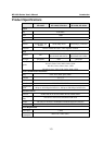
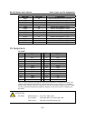
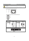
LED Name LED Color LED Function
DIO0 red Indicates that DIO is in “low” (0) status.
DIO1 red Indicates that DIO is in “low” (0) status.
DIO2 red Indicates that DIO is in “low” (0) status.
DIO3 red Indicates that DIO is in “low” (0) status.
TXD0 red Indicates that TXD0 has a signal.
RXD0 red Indicates that RXD0 has a signal.
DTR0 red Indicates that DTR0 has a signal.
CTS0 red Indicates that CTS0 has a signal.
DSR0 red Indicates that DSR0 has a signal.
DCD0 red Indicates that DCD0 has a signal.
RTS0 red Indicates that RTS0 has a signal.
TXD1 red Indicates that TXD1 has a signal.
RXD1 red Indicates that RXD1 has a signal.
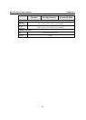
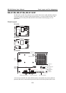
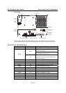
Pin Assignments
NE-4100T
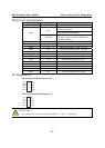
Pin Signal Pin Signal
1 ETx+ 14 PIO0
2 ETx- 15 PIO1
3 ERx+ 16 PIO2
4 ERx- 17 PIO3
5 10M LED 18 100M LED
6 TXD 19 DCD
7 RXD 20 DSR
8 RTS 21 DTR
9 CTS 22 GND
10 Reset 23 Ready LED
11 GND 24 +5V
12 GND 25 +5V
13 TXD1* 26 RXD1*
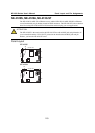
*Pins 13 and 26 control the NE-4100-ST Debug Serial COM Port’s TXD and RXD signals. The
location of the Debug Serial COM Port is shown on the previous page. This port is not needed
during normal operation. However, if the network fails and you need to configure your NE-4100T,
you may connect the Debug Serial COM Port, and then use the serial console to configure your
NE-4100T.
ATTENTION
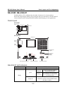
NE-4100T Ethernet Signals: ETx+, ETx-, ERx+, ERx-
Serial Signals: TXD, RXD, RTS, CTS, DCD, DSR, DTR
LED Controls: 10M LED, 100M LED, Ready LED