


NE-4100 Series User’s Manual Getting Started
3-4
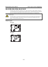
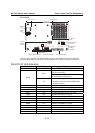
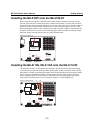
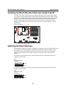
Installing the NE-4120S, NE-4120A onto the NE-4120-ST
The NE-4120S and NE -4120A modules are attached to the NE-4120-ST board using mounting
screws that are provided with the board. When attaching the module to the board, make sure that
the module is oriented so that the jumper banks on the module and the board are aligned as shown
below. Use the provided ribbon cables to connect jumper block J1 on the module to J9 on the
board, J2 on the module to J10 on the board, and J3 on the module to J7 on the board. When
plugging in each ribbon cable, make sure that the red key wire corresponds with pin 1 on each
jumper block.
1234
ON
DIP
910
1314
12
12
1
2
1
2
9
10
13
14
1
2
3
4
5
NE-4120-ST Starter Kit
NE-4120 Series
Module
J2
J10
J1 J9
1
2
3
4
5
J3
J7
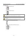
Selecting the Serial Interface
NE-4100 Series modules are available for different serial interfaces. The NE-4110S and NE-4120S
are designed for the RS-232 interface, and the NE-4110A and NE-4120A are designed for the
RS-422/485 interface. On the NE-4110-ST and NE-4120-ST evaluation boards, the Network
Enabler Interface jumper block is used to select the serial interface used for your particular
module.
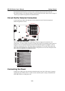
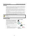
For the NE-4110S and NE-4120S, the evaluation board should be configured for the RS-232
interface, as shown below.
RS485
RS232
JP2
Network Enabler
Interface
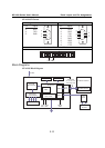
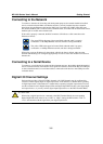
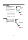
For the NE-4110A and NE-4120A, the evaluation board should be configured for the RS-485
interface, as shown below.
JP2
Network Enabler
Interface
RS485
RS232