


NE-4100 Series User’s Manual DIO Commands
D-6
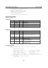
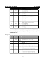
Byte # Descriptor Value Description
9 Data 0,1
2nd DIO channel to be written
0: set to input mode
1: set to output mode
10 Data 0,1
2nd DIO channel to be written
0: set to low
1: set to high
11 Data 0,1
3rd DIO channel to be written, optional
0: set to input mode
1: set to output mode
12 Data 0,1
3rd DIO channel to be written, optional
0: set to low
1: set to high
13 Data 0,1
4th DIO channel to be written, optional
0: set to input mode
1: set to output mode
14 Data 0,1
4th DIO channel to be written, optional
0: set to low
1: set to high
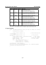
This command writes the status of a range of DIO channels, specified in bytes 5 and 6. The length
of the command depends on the number of channels to be written. For example, the 10-byte
command 6-2-0-6-0-1-0-0-1-1 requests DIO 0 be set to digital input mode and “low” status and
DIO 1 be set to digital output mode and “high” status. If you wanted to include a change of DIO 2
to digital output mode and “low” status, the 12-bye command sequence would be
6-2-0-8-0-2-0-0-1-1-1-0.
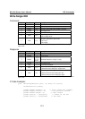
Response
Byte # Descriptor Value Description
1 Header 6 command number, fixed
2 Header 2 version, fixed
3 Header
0, 1, 2, 3,
4, 5, 6,
0xFF
command status/error code (0 = okay)
4 Header 4, 6, 8
data length, depends on the number of DIO channels
requested
5 Data
0, 1
1st requested DIO channel
0: channel has been changed to input mode
1: channel has been changed to output mode
6 Data
0, 1
1st requested DIO channel
0: channel status has been changed to low
1: channel status has been changed to high
7 Data
0, 1
2nd requested DIO channel
0: channel has been changed to input mode
1: channel has been changed to output mode