


NE-4100 Series User’s Manual Panel Layout and Pin Assignments
2-11
Pin Assignments
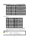
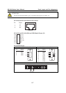
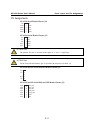
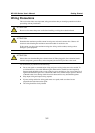
NE-4120S Serial Header Pinouts (J1)
9
7
5
3
1
10
8
6
4
2
NC
RTS0
GND
TxD0
DCD0
NC
CTS0
DSR0
DTR0
RxD0
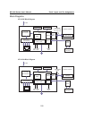
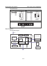
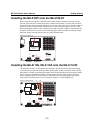
NE-4120A Serial Header Pinouts (J1)
9
7
5
3
1
10
8
6
4
2
NC
GND
NC
NC
NC
RxD-
TxD+
NC
RxD+
TxD-
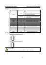
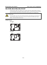
ATTENTION
The symbols “B” and “A” are often used in place of “+” and “-”, respectively.
ATTENTION
For the 2-wire RS-485 interface, pin 3 is for Data+ (B) and pin 4 is for Data- (A).
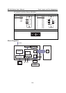
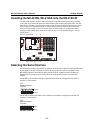
NE-4120S and NE-4120A Ethernet Header Pinouts (J3)
1
2
3
4
5
Tx+
Tx-
Rx+
Rx-
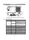
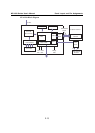
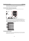
NE-4120S and NE-4120A DIO and LED Header Pinouts (J2)
9
7
5
3
1
10
8
6
4
2
11
13
12
14
Ready_LED
RxD1
Reset
100M_LED
10M_LED
VCC(+5V)
VCC(+5V)
TxD1
DIO3
DIO2
DIO1
DIO0
GND
GND