


NE-4100 Series User’s Manual Getting Started
3-7
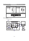
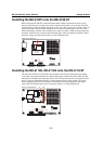
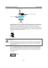
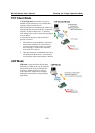
Digital Output
DO0 DO1 DO2 DO3
DI DO
0
1
2
3
DI/O Mode
DO0 DO1 DO2 DO3
1234
ON
DIP
Digital Input
0123
ON: Low
OFF: High
: Low
: High
DI/O Selectable Jumper
Digital Input Signal Setting Switch
DI/O Terminal Block
Digital Output LEDs
DI/O Mode jumpers 0 through 3 correspond with DIO channels 0 through 3. The jumper’s position
determines whether the corresponding channel is linked to a DIP switches or to an LED. When a
channel’s jumper is set to the DI position, the channel’s input signal is controlled by the
corresponding Digital Input DIP switch. When the jumper is set to the DO position, the channel’s
output signal is routed to the corresponding Digital Output LED. For example, if DIO channel 0 is
operating as a digital input channel, setting DI/O Mode jumper 0 to the DI position enables the use
of DIP switch 0 as that channels’ input device.
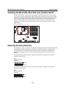
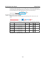
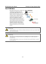
DI DO
0
1
2
3
DI/O Mode
ATTENTION
The DI/O Mode jumpers are used to tell the evaluation board whether to use the Digital Output
LEDs or the Digital Input DIP switches. The jumpers do not control the channel’s mode. Input
and output mode is configured through the web, serial, or Telnet console, or through Network
Enabler Administrator.
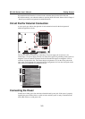
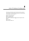
When using a Digital Input DIP switch as your input device, the “ON” position corresponds to
“Low” status and the “OFF” position corresponds to “High” status. The result can be monitored
with the Network Enabler Administrator or with the web console. Make sure all DIP switches are
set to “OFF” if you are using your own digital input device that is connected to the evaluation
board’s terminal block.
1234
ON
DIP
Digital Input
0123
ON: Low
OFF: High