


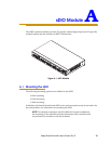
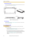
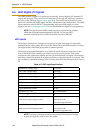

Appendix A - sDIO Module
100 Adept SmartController User’s Guide, Rev. E
3. Select option 2.
2 - Edit system configuration
Then, press ENTER to continue.
4. Select either option 5 or option 6:
5 - Change DIGITAL_INPUT configuration
or
6 - Change DIGITAL_OUTPUT configuration
Then, press ENTER to continue.
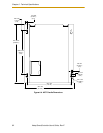
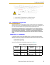
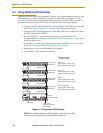
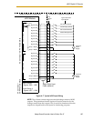
5. The program will step you through the process of adding a new statement to
assign the appropriate I/O signals to a block, and then to a byte (1 to 4) within a
block. With the sDIO, the first 8 input channels are mapped to byte 1, the second 8
input channels to byte 2, and so on. See sDIO Signal Mapping Example 1. Using
this process, you must assign groups of signal numbers to bytes 1 to 4 for each
block. See the sDIO Signal Mapping Example 2 for the input settings of a system
with two sDIO modules. When you are done editing the I/O choose not to add a
new statement.
6. Save the changes, if you are satisfied with your choices.
7. Continue to select 0 to return through the higher menus. Select 0 once more to exit
to the system monitor.
8. Disconnect your AdeptWindowsPC or serial communication session to the
SmartController.
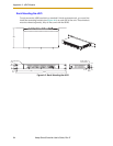
9. Cycle the 24VDC input power to the sDIO.
10. Cycle the 24VDC input power to the SmartController.
11. Reconnect your AdeptWindowsPC or serial communication session to the
SmartController.