


Chapter 3 - SmartController Operation
44 Adept SmartController User’s Guide, Rev. E
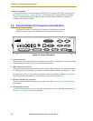
AUTO Boot
When using the SmartController in an AUTO Boot configuration, DIP switch SW1 must
be set to the switch settings shown in row #5 of Table 3-3 and the NVRAM switches set for
AUTO boot.
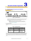
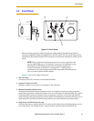
3.5 SmartController Serial I/O Connectors
The SmartController CS has two serial I/O connectors, an RS-232/Term and an
RS-422/485 port. See Figure 3-1 on page 37 for the connector locations.
The SmartController CX has two additional serial connectors, RS-232-1 and RS-232-2. See
Figure 3-2 on page 40 for the connector locations.
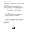
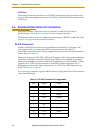
RS-232 Connectors
All three of the RS-232 connectors are 9-pin DB9 male (standard PC) connectors. The
user-supplied cable to connect to the RS-232 connectors should be a DB9, F/F,
null-modem data transfer cable. The pin assignments are the same for all three connectors
and are shown in Table 3-4.
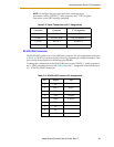
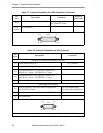
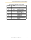
These ports support the DTR, DCD, RTS, and CTS signals used for hardware handshaking
(also known as modem control). By default, these signals are not enabled. To configure
hardware handshaking and other communication parameters, use the CONFIG_C utility
program, the V
+
FSET program instruction, or the FSET monitor command. The V+
designations for these ports when referenced in a V
+
ATTACH or FSET instruction are
shown in Table 3-5 on page 45.
If you are using a customer-supplied ASCII terminal, it plugs the RS-232/Term connector
on the SmartController.
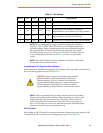
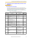
Table 3-4. RS-232 Connector Pin Assignments
Pin Signal Type
1DCD Input
2RXD Input
3TXD Output
4DTR Output
5GND Ground
6NC
7RTS Output
8CTS Input
9NC