


Chapter 2 - SmartController Installation
30 Adept SmartController User’s Guide, Rev. E
NOTE: If you are replacing an existing CF, the original must be sent to
Adept for replacement. Press the button inside the CF compartment to
eject the original card, remove it, and return it to Adept. Contact Adept
Customer Service for assistance.
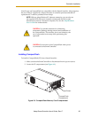
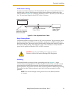
3. Carefully remove the CF from the READ ME FIRST box or shipping container.
Locate the CF slot and position the card so its connector is facing towards the
SmartController and the label is facing up.
4. Insert the CF into the SmartController.
NOTE: Your licenses were installed onto the CF at the factory when it was
initialized. Your licenses must be reinstalled onto a new CF by using the
provided passwords and the V
+
INSTALL monitor command. These
passwords are provided in a box or folder labeled READ ME FIRST.
Once installed, Adept recommends that you do not repeatedly remove and insert the CF.
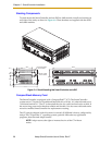
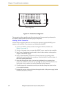
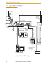
Connecting Power
The SmartController and sDIO require filtered 24VDC power.
NOTE: Users must provide their own power supply. Make sure the power
cables and power supply conform to the specifications below.
24VDC Power Specifications
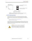
NOTE: The power requirements for the user-supplied power supply will
vary depending on the configuration of the SmartController and
connected devices. A minimum configuration of the controller, front
panel and MCP will require 1A at 24VDC. However, a 24V, 5A power
supply is recommended to allow for additional current draw from
connected devices, such as external IEEE 1394 devices and digital I/O
loads.
Table 2-2. Specifications for 24VDC User-Supplied Power Supply
Customer-Supplied Power
Supply
24VDC, 120W (5A).
Circuit Protection Not more than 8A (below the
amperage rating of the cable used).
Power Cabling 1.5 - 1.85 mm2 (16-14 AWG),
maximum length 10 meters
Shield Termination Braided shield connected to “-”
terminal at the appropriate XDC
connector.