


Appendix A - sDIO Module
96 Adept SmartController User’s Guide, Rev. E
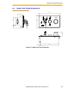
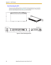
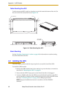
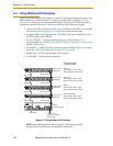
Table Mounting the sDIO
To table mount the sDIO, install two brackets on each side near the bottom of the unit. Use
the screws from the accessories kit; see Figure A-4.
Figure A-4. Table Mounting the sDIO
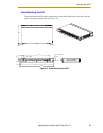
Stack Mounting
See the “Stacking Components” section on page 28 for information on stack mounting
the sDIO and SmartController.
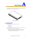
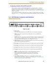
A.2 Installing the sDIO
The following procedure details the steps required to successfully install the sDIO.
To install the sDIO module:
1. Remove the sDIO module from its box and set it up near the robot or mount it as
described in “Mounting the sDIO” on page 93.
2. Ensure that the 24VDC input power to the SmartController is disengaged.
3. Connect a 24VDC cable from the XDC2 port on the SmartController to the XDC1
port on the sDIO. Continue to daisy-chain the input power from each sDIO to the
next. See “Connecting Power” on page 30 for cabling requirements.
NOTE: European installations must be in accordance with the EN60204
standard.
R 3.6
16.3
391.9
16.0
378.7
24.9
24.1
120.8
21.7
4X 40356-00001
12.1
29.5
120.9
4X M3 x 6MM
BOTH SIDES