


sDIO Digital I/O Signals
Adept SmartController User’s Guide, Rev. E 105
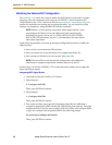
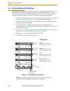
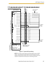
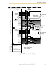
Figure A-7. Typical sDIO Input Wiring
NOTE: The off state current range exceeds the leakage current of sDIO
outputs. This guarantees that the inputs will not be turned on by the
leakage current from the outputs. This is useful in situations where the
outputs are looped-back to the inputs for monitoring purposes.
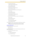
Adept-Supplied Equipment
Customer-Supplied Equipment
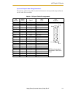
Signal 1033
Part Present Sensor
15
Signal 1034
Feeder Empty Sensor
6
Signal 1035
Part Jammed Sensor
16
Signal 1036
Sealant Ready Sensor
7
Signal 1037
17
Signal 1038
8
Signal 1039
18
Signal 1040
9
Group 1 Return
25
Group 1 Return
26
Signal 1041
10
Signal 1042
1
Signal 1043
11
Signal 1044
2
Signal 1045
12
Signal 1046
3
Signal 1047
13
Signal 1048
4
Group 2 Return
19
Group 2 Return
20
Customer
Power
Supply
+
–
+
–
Customer
Power
Supply
sDIO Module
Input Group 1
Wiring
Terminal
Block
Typical Customer
Input Signals
Input Group 2
X3 Connector – 26-Pin Female D-Sub
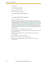
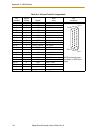
Input Group 3
Signals 1049 – 1056
Input Group 4
Signals 1057 – 1064
X4 Connector –
26-Pin Female D-Sub
Adept Digital Input
Cable (optional)
(equivalent circuit)