


Chapter 4 - AdeptVision sAVI Option
74 Adept SmartController User’s Guide, Rev. E
4.5 Camera Cable Pin and Signal Information
This section provides the pin and signal information for the connectors and cables
associated with the AdeptVision product.
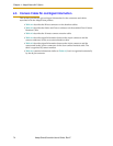
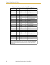
• Table 4-1 describes the Hirose connector on the breakout cables.
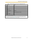
• Table 4-2 describes the Strobe and Power connector on the standard Four-Camera
Breakout Cable.
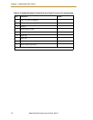
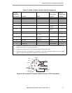
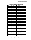
• Table 4-3 describes the 10-meter camera extension cable.
• Table 4-4 describes signal information between the 44-pin connector and the
camera connectors for the two-camera breakout cable.
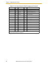
• Table 4-5 describes signal information between the 44-pin connector and the
camera and strobe/power connectors for the four-camera breakout cable. The
table is organized by camera number.
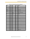
• Table 4-6 contains information similar to Table 4-5, but it is organized numerically
by the 44-pin connector.