


Connecting Customer-Supplied Safety and Power Control Equipment
Adept SmartController User’s Guide, Rev. E 49
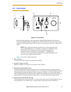
3.7 Connecting Customer-Supplied Safety and Power Control
Equipment
Connecting Equipment to the System
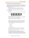
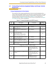
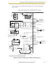
The connection of the customer-supplied safety and power control equipment to the
system is done through the XUSR and XFP connectors on the SmartController. The XUSR
connector (25-pin) and XFP (15-pin) connector are both female D-sub connectors located
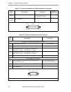
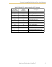
on the front panel of the SmartController. Refer to Table 3-7 for the XUSR pin-out
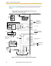
explanations. Refer to Table 3-8 on page 50 for the XFP pin-out explanations. See Figure
3-5 on page 53 for the XUSR wiring diagram.
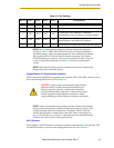
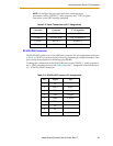
Table 3-7. Contacts Provided by the XUSR Connector
Pin
Pairs
Description Comments
Shorted if
NOT Used
Voltage-Free Contacts Provided by Customer
1, 14
User E-Stop CH 1 (mushroom PB,
safety gates, etc.).
N/C contacts
Yes
2,15
User E-Stop CH 2 (same as pins 1
and 14).
N/C contacts
Yes
3,16
Line E-Stop (used for other robot or
assembly line E-Stop
interconnection. Does not affect
E-Stop indication (pins 7, 20.))
N/C contacts
Yes
4,17
Line E-Stop (Same as pins 3 and 16.
See above comment.)
N/C contacts
Yes
5,18
Muted safety gate CH 1 (causes
E-stop in AUTOMATIC mode only).
N/C contacts
Yes
6,19
Muted Safety Gate CH 2 (same as
pins 5 and 18).
N/C contacts
Yes
Voltage-Free Contacts provided by Adept
7,20
E-Stop indication CH 1. Contacts are closed when
Front Panel, MCP, and
customer E-Stops are not
tripped
8,21
E-stop indication CH 2 (same as pins
7 and 20.
Contacts are closed when
Front Panel, MCP, and
customer E-stops are not
tripped
9,22
MANUAL/AUTO indication CH 1 Contacts are closed in
AUTOMATIC mode