


Adept SmartController User’s Guide, Rev. E 37
SmartController Operation 3
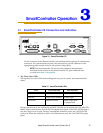
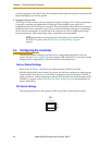
3.1 SmartController CS Connectors and Indicators
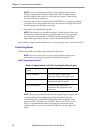
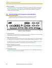
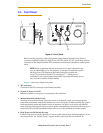
Figure 3-1. SmartController CS
All the connectors on the SmartController use standard density spacing, D-subminiature
connectors. For customization purposes, the user needs to provide connectors of the
appropriate gender and pin count or use optional Adept cables.
NOTE: The SmartController CX has all of the connectors and indicators
described in this section for the SmartController CS, plus additional ones
covered in Section 3.2 on page 40.
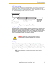
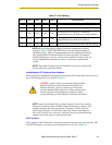
1. Top Three Status LEDs
The top three two-color LEDs indicate diagnostic test, power control, and communication
status.
During system bootup, the red OK/SF and HPE/ES LEDs are lit and the red LAN/HD LED
blinks. After system bootup, the OK/SF LED should show green. If the HPE/ES LED shows
red, the E-Stop circuit is open. During CompactFlash reads and writes, the LAN/HD LED
pulses red. When the controller is active on an Ethernet network, the LAN/HD LED pulses
green.
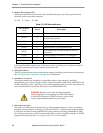
Table 3-1. SmartController LEDs
LED Green Indicates Red Indicates
OK/SF System OK System Fault
HPE/ES High Power Enabled E-Stop Open
LAN/HD Ethernet Access Read/Write from
CompactFlash
1 2 3
RS-422/485
XUSR
XSYS
SF
XMCP
1.1
SmartController CS
LANHPE
OFF
24V 5A
ON
RS-232/TERM
XFP
HDES
XDIO
Eth 10/100
*S/N 1000-XXXXX*
SW1
Device Net
SmartServo
XDC1 XDC2
- + - +
1 2 3 4
OK
R
1.2