


Chapter 4 - AdeptVision sAVI Option
72 Adept SmartController User’s Guide, Rev. E
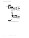
4.4 Installing Camera Cables
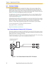
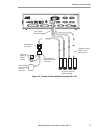
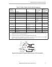
Figure 4-3 on page 73 shows the installation of a typical four-camera RS-170 breakout
cable and the associated hardware in a SmartController CX system. See the AdeptVision
User’s Guide for information on mounting cameras and strobes in your system.
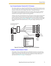
Connecting the Cables to the RS-170 Standard Camera
This section describes the steps for connecting the cables between the sAVI board and the
RS-170 Cameras.
1. Turn off the SmartController CX.
2. Connect the camera to a 10m camera cable.
3. Connect the 10m camera cable to the appropriate connection on the camera
breakout cable.
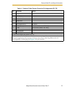
4. Connect the power supply and strobe lamps through the 9 pin D-sub connector
(see Figure 4-2 on page 71 and Table 4-2 on page 76 for pin assignments).
5. Connect the camera breakout cable to the Camera connector on the
SmartController CX.
CAUTION: Turn off the controller before installing or
removing a camera or cable. Failure to do this may
damage the sAVI board.
CAUTION: When using the four-camera breakout cable,
you must provide 12 VDC power at sufficient current for
the type and quantity of cameras you are using. See the
documentation supplied with your cameras for
information on current requirements.