


Chapter 2 - SmartController Installation
32 Adept SmartController User’s Guide, Rev. E
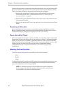
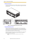
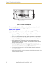
Figure 2-7. Chassis Grounding Point
The mounting of the controller and all terminations in Europe must be performed in
accordance with EN 60204 to maintain proper compliance.
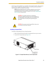
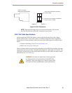
Installing 24VDC Connectors
Use the Adept-supplied connectors to connect the customer-supplied 24VDC power
supply to the controller. The connectors are Weidmuller #169042.
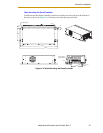
1. Locate two 24VDC connectors that are shipped with the controller. See
Figure 2-8 on page 33.
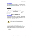
2. Use 14 or 16 gauge wires to connect the 24VDC power supply to the controller.
3. Strip 7 mm of insulation from the end of the wire that connects to the positive
output of the 24VDC supply.
4. Insert a small flat-blade screwdriver (2.5 mm) into the top opening on the
right-hand (positive) side of the connector. Push the blade in until the clamp in
the lower opening folds back.
5. Insert the stripped end of the wire into the right-hand lower opening, then
remove the screwdriver from the top opening. The clamp will close on the wire.
Pull on the wire to confirm it is securely attached in the connector.
6. Visually inspect the connection to make sure that the clamp has closed on the
wire, not the insulation.
7. Repeat this process for the wire from the negative side of the power supply to the
left-hand side of the connector.
Grounding Point