


Configuring a Single sDIO
Adept SmartController User’s Guide, Rev. E 97
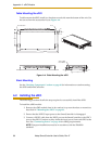
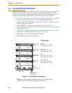
4. Connect an IEEE 1394 cable from one of the SmartServo ports (1.1 or 1.2) on the
SmartController to one of the IEEE 1394 ports on the sDIO. Continue to
daisy-chain the IEEE 1394 power from each sDIO to the next.
5. Connect the 24 VDC input power to the SmartController.
6. Connect a user-supplied ground wire to earth ground.
A.3 Configuring a Single sDIO
The SmartController is preconfigured to support one sDIO module. Its configuration is
based upon an I/O block assignment method that uses 4 bytes per block and 8 signals per
byte. Thus, each byte within a block represents an eight signal range of I/O.
Block numbers for general digital I/O can range from 16 to 31; the default is 16. Input
blocks and output blocks are numbered independently so you can use the same number
for both an input and an output block. You must be sure that the block number you
specify is not used for the same type of block in any other sDIO module or RIO in your
system.
Default sDIO I/O Configuration
A single sDIO module can be used with the default I/O signal configuration and no
additional configuration is required. The following signal groups are predefined for use:
• Input signals 1033 to 1064
• Output signals 0033 to 0064
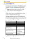
The default configuration consists of the settings shown in Table A-1.
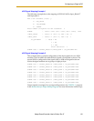
WARNING: Remove power from the SmartController
before plugging in or unplugging any IEEE-1394 cables to
SmartServo IEEE-1394 connectors. Failure to remove
power could result in unpredictable behavior by the
system.
Table A-1. Default I/O Configuration for sDIO
Input Signal
Numbers
Block Byte
Output Signal
Numbers
Block Byte
1033 to 1040 16 1 0033 to 0040 16 1
1041 to 1048 16 2 0041 to 0048 16 2
1049 to 1056 16 3 0049 to 0056 16 3
1057 to 1064 16 4 0057 to 0064 16 4