


Connecting Customer-Supplied Digital I/O Equipment
Adept SmartController User’s Guide, Rev. E 61
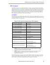
Output Signals
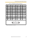
The XDIO connector handles output signals 0001 to 0008. Refer to Table 3-11 for output
specifications. The locations of the signals on the connector are shown in Table 3-12 on
page 63. The XDIO connector provides separate positive and negative connections for
each channel (no internal common connections). This allows the choice of wiring for
current-sourcing or current-sinking modes.
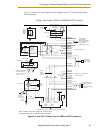
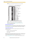
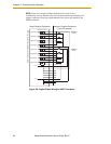
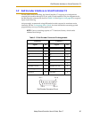
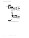
Figure 3-8 shows two examples of different connections to the digital outputs on the
XDIO connector. The examples are negative common and positive common using the
internal 24V and ground connections.
Example 1: outputs 0001 to 0004 are shown with positive common.
Example 2: outputs 0005 to 0008 are shown with negative common.
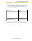
Table 3-11. DIO Output Specifications (XDIO connector)
Operating voltage range 0 to 24VDC
Operational current range, per channel I
out
≤ 100 mA, short-circuit
Protected
V
drop across output in “on” condition V drop ≤ 2.7 V at 100 mA
V
drop ≤ 2.0 V at 10 mA
Output off leakage current I
out
≤ 600 µA
Turn on response time (hardware)
Software scan rate/response time
3 µsec maximum
16 ms scan cycle/ 32 ms max.
response time
Turn off response time (hardware)
Software scan rate/response time
200 µsec maximum
16 ms scan cycle/ 32 ms max.
response time