


Configuring a Single sDIO
Adept SmartController User’s Guide, Rev. E 101
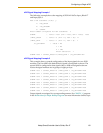
sDIO Signal Mapping Example 1
The following example shows the mapping of SIGNAL 1065 to Input_Block 17
and Input_Byte 1.
Add a new statement (Y/N)? y
1: POS_LATCH
2: VIS_TRIGGER
3: SIGNAL
Enter number of keyword for new statement: 3
SIGNAL : Value = 1001 (min = 1001, max = 1505): 1065
/INPUT_BLOCK : Value = 0 (min = 0, max = 31): 17
/INPUT_BYTE : Value = 1 (min = 1, max = 4): 1
/IO_OPTIONAL : Value = NO
1 > NO
2 > YES
Enter selection: 1
SIGNAL 1065 = "/INPUT_BLOCK 17/INPUT_BYTE 1 /IO_OPTIONAL NO"
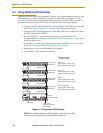
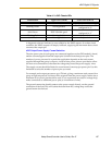
sDIO Signal Mapping Example 2
This example shows a sample configuration of the Input signals for two sDIO
modules. The first sDIO uses default block 16 and is configured as shown. The
second sDIO is configured so that signals 1065 to 1098 are assigned as shown.
Notice the signal numbers are in groups of eight per byte.
SIGNAL 1033 = "/INPUT_BLOCK 16 /INPUT_BYTE 1 /IO_OPTIONAL YES"
SIGNAL 1041 = "/INPUT_BLOCK 16 /INPUT_BYTE 2 /IO_OPTIONAL YES"
SIGNAL 1049 = "/INPUT_BLOCK 16 /INPUT_BYTE 3 /IO_OPTIONAL YES"
SIGNAL 1057 = "/INPUT_BLOCK 16 /INPUT_BYTE 4 /IO_OPTIONAL YES"
SIGNAL 1065 = "/INPUT_BLOCK 17 /INPUT_BYTE 1 /IO_OPTIONAL YES"
SIGNAL 1073 = "/INPUT_BLOCK 17 /INPUT_BYTE 2 /IO_OPTIONAL YES"
SIGNAL 1081 = "/INPUT_BLOCK 17 /INPUT_BYTE 3 /IO_OPTIONAL YES"
SIGNAL 1089 = "/INPUT_BLOCK 17 /INPUT_BYTE 4 /IO_OPTIONAL YES"
Output signals are assigned in a corresponding manner. See CONFIG_C program
in the Instructions for Adept Utility Programs for more information on this topic.