


89
Auxiliary Area Data Section 4-5
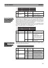
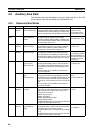
4-5-2 Read/Write Bits (User Settings)
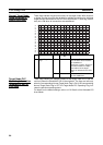
A417 A41700 to
A41715
CPU Bus Unit Error,
Unit Number Flags
When an error occurs in a data exchange between
the CPU Unit and a CPU Bus Unit, the CPU Bus
Unit Error Flag (A40207) and the corresponding flag
in A417 are turned ON. Bits 00 to 15 correspond to
unit numbers 0 to F.
The ERR/ALM indicator on the front of the CPU Unit
will flash, but CPU operation will continue.
0: No error
1: Error
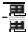
A427 A42700 to
A42715
CPU Bus Unit Set-
ting Error, Unit
Number Flags
When a CPU Bus Unit Setting Error occurs, A40203
and the corresponding flag in A27 are turned ON.
Bits 00 to 15 correspond to unit numbers 0 to F.
The ERR/ALM indicator on the front of the CPU Unit
will flash, but CPU operation will continue.
0: No setting error
1: Setting error
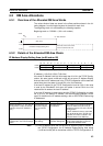
Word Bits Name Description Settings
A501 A50100 to
A50115
CPU Bus Unit
Restart Bits
Bits A50100 through A50115 can be turned ON to
reset CPU Bus Units number #0 through #15,
respectively.
Note The CPU Bus Unit Initializing Flags (A30200
to A30215) will turn ON when initialization of
the Units begins and turn OFF when it is com-
pleted.
Note When turning ON the CPU Bus Unit Restart
Bit from a ladder program, use the SET
instruction.
OFF to ON:
Unit restarted.
Automatically turned
OFF by system after
restart processing
has been completed.
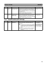
Word(s) Bit(s) Name Function Settings