


371
Troubleshooting with FINS Response Codes Section 14-6
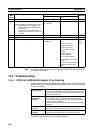
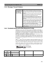
14-5-5 Message Timeout Problems
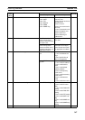
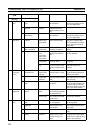
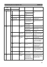
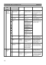
14-6 Troubleshooting with FINS Response Codes
The cause of errors that occur when using the SEND(090), RECV(098), or
CMND(490) instructions can be identified from the response codes. (Refer to
the description of Communications Port Completion Codes in 8-6-4 Writing
Programs for the storage locations of response codes generated by the
SEND(090), RECV(098), or CMND(490) instructions.)
This section describes the completion codes produced by EtherNet/IP Units.
For details on completion codes produced by CPU Units, other CPU Bus
Units, or computers equipped with FINS services, refer to the device’s opera-
tion manual.
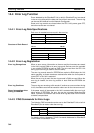
The 6
th
, 7
th
, and 15
th
bits of the response codes have specific functions. The
6
th
bit will be ON when a non-fatal error has occurred in the PLC at the remote
node; the 7
th
bit will be ON when a fatal error has occurred in the PLC at the
remote node; and the 15
th
bit will be ON when a network relay error has
occurred. The following table explains the meaning of the completion codes.
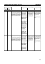
Timeout errors
occur frequently in
message services
(CIP UCMM, CIP
Class 3, or FINS).
• When there is a high load in the tag data link, and the CPU
Unit’s cycle time is relatively long or there are messages
coming in from many nodes, the message service response
time may be delayed and messages may be discarded occa-
sionally.
• In this case, the communications load must be reduced by
increasing (slowing) the tag data link’s RPI, reducing the
message load, or increasing the timeout value.
• The tag data link’s bandwidth usage can be checked on the
Monitor Device Window’s Ethernet Information Tab Page.
Refer to 14-1 Checking Status with the Network Configurator
for details.
• The error log error codes that indicate discarded messages
(insufficient memory) due to heavy communications loads
are 0117, 0119, 0123, 0125, 03C2 (detail code @@08,
@@09, or @@0A), 03C3, and 03D2. Refer to 14-1 Checking
Status with the Network Configurator for details on reading
the error codes on the Error History Tab Page.
• For information on preventing high loads in FINS communi-
cations, refer to 8-7 Precautions on High Traffic in FINS
Communications.
7654321076543210
First byte
Second byte
Bit
PLC Fatal Error Flag PLC Non-fatal Error Flag
Relay Error Flag
Main response code (RES)
Sub response code (SRES)
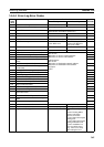
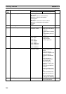
Main response
code
Sub response code Item to check Likely cause Corrective action
Value and
meaning
Value and meaning
00 Normal
completion
00 --- --- --- ---