


73
CIO Area Allocations Section 4-2
Target Node PLC
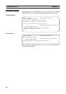
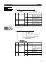
Error Information
(EtherNet/IP Unit to
CPU Unit) (n + 6 to n +
9)
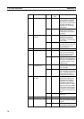
These words show the error status (logical OR of fatal and non-fatal errors) of
the target node PLCs that are connected with the EtherNet/IP Unit as the orig-
inator. This status information is enabled when the PLC status is included in
the communications data in both the originator and target node.
These words show the error status of nodes 0 to 63 only. If it is necessary to
show the error status of nodes higher than node 63, select “user settings” as
the layout pattern. For details, refer to 4-4 User Settings Area.
The flags are valid only when the corresponding Normal Target Node Flag is
ON. If the corresponding Normal Target Node Flag is OFF, the Target Node
PLC Error Flag indicates the previous error status.
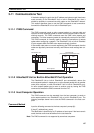
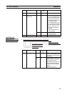
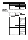
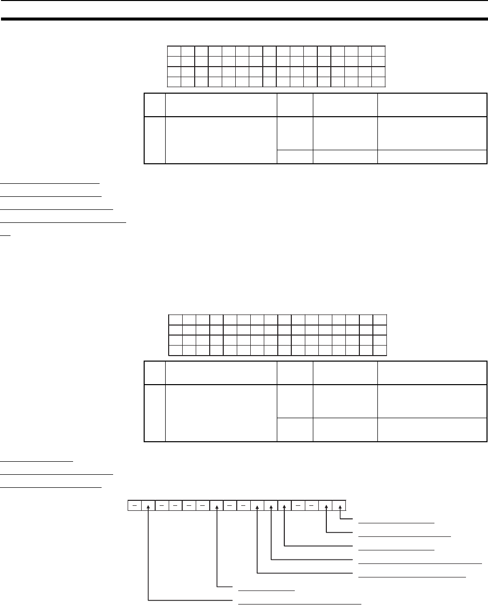
Unit Status 1
(EtherNet/IP Unit to
CPU Unit) (n + 10)
Bit Name Status Manipulated
by
Unit operation
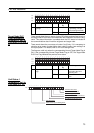
--- Target Node PLC Operat-
ing Flags
ON Unit The corresponding PLC
is operating. (The pro-
gram is being executed.)
OFF Unit The PLC is not operating.
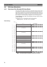
n+2
n+3
n+4
n+5
15 14 13 12 11 10 9 8 7 6 5 4 3 2 1 0
15 14 13 12 11 10 9 8 7 6 5 4 3 2 1 0
31 30 29 28 27 26 25 24 23 22 21 20 19 18 17 16
47 46 45 44 43 42 41 40 39 38 37 36 35 34 33 32
63 62 61 60 59 58 57 56 55 54 53 52 51 50 49 48
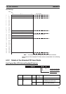
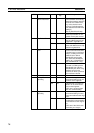
Bit Name Status Manipulated
by
Unit operation
--- Target Node PLC Error
Flags
ON Unit A fatal or non-fatal error
occurred in the corre-
sponding PLC.
OFF Unit No error occurred in the
PLC.
15 14 13 12 11 10 9 8 7 6 5 4 3 2 1 0
n+6 15 14 13 12 11 10 9 8 7 6 5 4 3 2 1 0
n+7 31 30 29 28 27 26 25 24 23 22 21 20 19 18 17 16
n+8 47 46 45 44 43 42 41 40 39 38 37 36 35 34 33 32
n+9 63 62 61 60 59 58 57 56 55 54 53 52 51 50 49 48
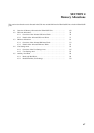
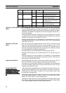
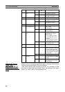
n+10
Network Error Occurred
Unit Memory Error
Communications Controller Error
Link OFF Error
Status Area Layout Setting Error
Unit Error Occurred
IP Address Duplication Error
15 14 13 12 11 10 9 8 7 6 5 4 3 2 1 0