


213
Using FINS Applications Section 8-5
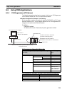
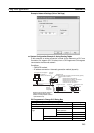
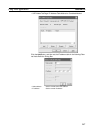
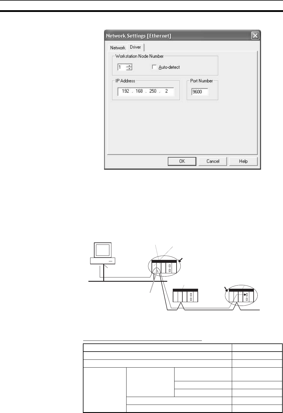
Example: Network Settings (Driver Tab Page)
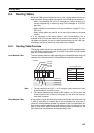
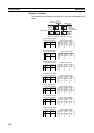
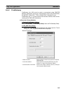
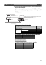
■ System Configuration Example 2: Using Routing Tables
In this example, an online connection is made via the Ethernet to a PLC on a
Controller Link network (PLC 3 below) from a CX-Programmer/CX-Integrator
connected to the Ethernet network.
Conditions
• FINS/UDP method
• IP address conversion: Automatic generation method (dynamic)
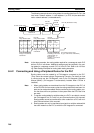
CX-Programmer's Change PLC Dialog Box
Settings for target PLC (PLC3)'s Change PLC Dialog Box Setting
PLC name PLC3
Network classification Ethernet
Network Tab
Page
FINS destination FINS transmission
source address
1
Network number 2
Node address 3
Frame length 2,000 bytes
Response monitor time 2 seconds
CX-Programmer/CX-Integrator
Ethernet port
Node address: 1
IP address: 192.168.250.1
Ethernet or EtherNet/IP
(network address 1)
Routing
according to
routing table
Controller
Link Unit
EtherNet/IP Unit
IP address conversion: Automatic generation method (dynamic)
Gateway between networks
PLC1
Controller Link Unit
Target PLC
Controller Link Unit
Node address 2
Node address 3
Controller Link
(
network address 2
)
PLC2
PLC3
EtherNet/IP Unit node address: 2
EtherNet/IP Unit IP address: 192.168.250.2
EtherNet/IP Unit unit number: 0
Controller Link Unit node address: 1
Controller Link Unit unit number: 1
Routing to final network address 2
requires relaying through node
address 2 of relay network address
1 (EtherNet/IP Unit).