


210
Routing Tables Section 8-4
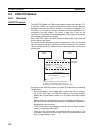
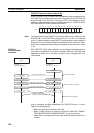
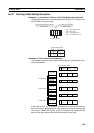
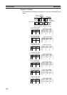
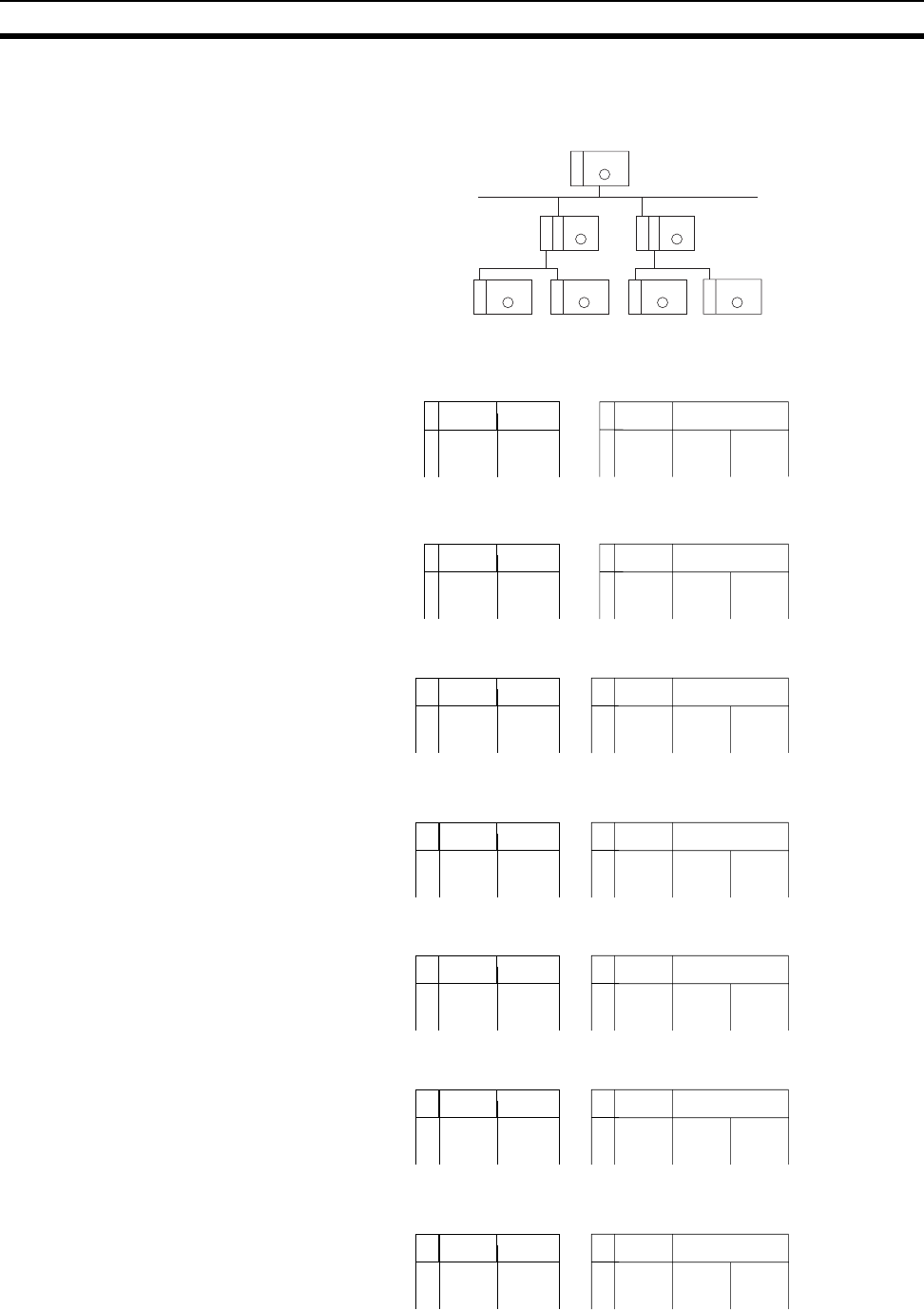
■ Example 3: All Nodes
This example uses the following configuration to show the routing tables for all
nodes.
PLC
5
PLC
1
E
I
P
PLC
2
C
L
K
E
I
P
PLC
3
E
I
P
S
L
K
C
PLC
4
C
PLC
6
PLC
7
L
K
L
K
S
L
K
S
L
K
Unit #5
Node #6
Network #10
Unit #4
Node #5
Network #30
Unit #0
Node #1
Unit #1
Node #2
Unit #5
Node #5
Unit #6
Node #10
Network #20
Unit #3
Node #4
Unit #2
Node #3
Unit #7
Node #15
No.
1
2
3
No.
1
2
3
010 05
020 010 004
030 010 005
No.
1
2
3
No.
1
2
3
010 03
030 010 005
No.
1
2
3
No.
1
2
3
010 04
020 010 004
No.
1
2
3
No.
1
2
3
020 00
010 020 003
030 020 003
No.
1
2
3
No.
1
2
3
020 01
010 020 003
030 020 003
No.
1
2
3
No.
1
2
3
030 05
010 030 015
020 030 015
No.
1
2
3
No.
1
2
3
030 06
010 030 015
020 030 015
020 02
030 07
PLC #1 Routing Table
(Local network table) (Relay network table)
Local
network
CPU Bus
Unit No.
End
network
Relay
network
Relay
node
PLC #2 Routing Table
PLC #3 Routing Table
PLC #4 Routing Table
PLC #5 Routing Table
PLC #6 Routing Table
PLC #7 Routing Table
(Relay network table)
(Relay network table)
(Relay network table)
(Relay network table)
End
network
Relay
network
Relay
node
End
network
Relay
network
Relay
node
End
network
Relay
network
Relay
node
End
network
Relay
network
Relay
node
(Local network table)
(Local network table)
(Local network table)
(Local network table)
(Local network table)
(Local network table)
Local
network
CPU Bus
Unit No.
Local
network
CPU Bus
Unit No.
Local
network
CPU Bus
Unit No.
Local
network
CPU Bus
Unit No.
Local
network
CPU Bus
Unit No.
Local
network
CPU Bus
Unit No.
End
network
Relay
network
Relay
node
End
network
Relay
network
Relay
node
(Relay network table)
(Relay network table)