


152
Setting Tag Data Links Section 6-2
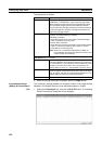
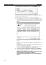
• Tag Set Name: If the Wizard is used, the names will be automatically
assigned using consecutive IP addresses in the following form for both
input and output tags: TagSet1_192168.250.1. There is no reason to be
concerned with these names. If the Wizard is not used, then names will
not be automatically assigned and they must be entered directly into the
data link table.
• Total Size: The total number of words in areas 1 and 2. This value is auto-
matically displayed after the sizes of areas 1 and 2 are entered.
• Node: For an input tag, this is the IP address of the node that provides the
output. For an output tag, “-” will be entered automatically.
• Target Variable: The target tag set name. For an input tag, this is the
name of the target set that provides the output. For an output tag, “-” will
be entered automatically.
• RPI (ms): The requested packet interval for an input tag. For an output
tag, “-” will be entered automatically.
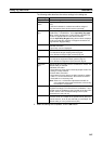
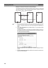
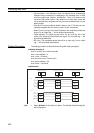
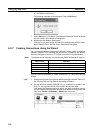
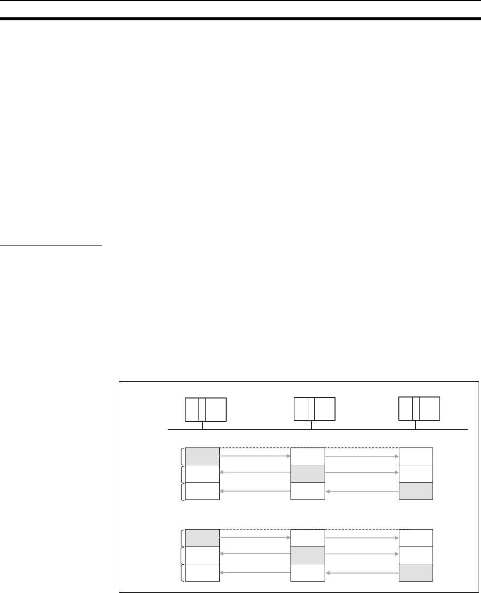
Setting Procedure The setting procedure is described here along with setting examples.
■ Setting Example A
Area 1 memory area = Work Area (W)
Area 1 start address = 0
Area 1 size = 50 words
Area 2 memory area = DM Area (D)
Area 2 start address = 50
Area 2 size = 100 words
■ Allocations
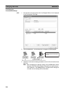
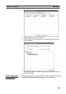
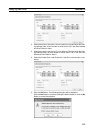
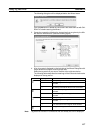
1,2,3... 1. Select Wizard from the Data Link Menu. The Datalink Wizard Dialog Box
will be displayed.
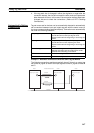
Area 1
Node 1
(IP address: 192.168.250.1)
Area 2
#1
#2
#3
#1
#2
#3
#3
#1
#2
Node 3
(IP address: 192.168.250.3)
#3
#1
#2
#2
#1
#3
Node 2
(IP address: 192.168.250.2)
#2
#1
#3
EtherNet/IP
W0
50 words
W50
50 words
W100
50 words
D50
100 words
D150
100 words
D250
100 words
W0
W0
D50 D50