


286
I/O Response Time in Tag Data Links Section 10-3
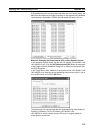
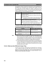
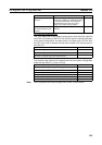
The following table gives the items required to find the I/O response time and
values used in calculations for this system configuration.
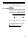
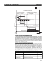
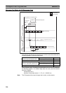
Maximum Tag Data Link I/O Response Time
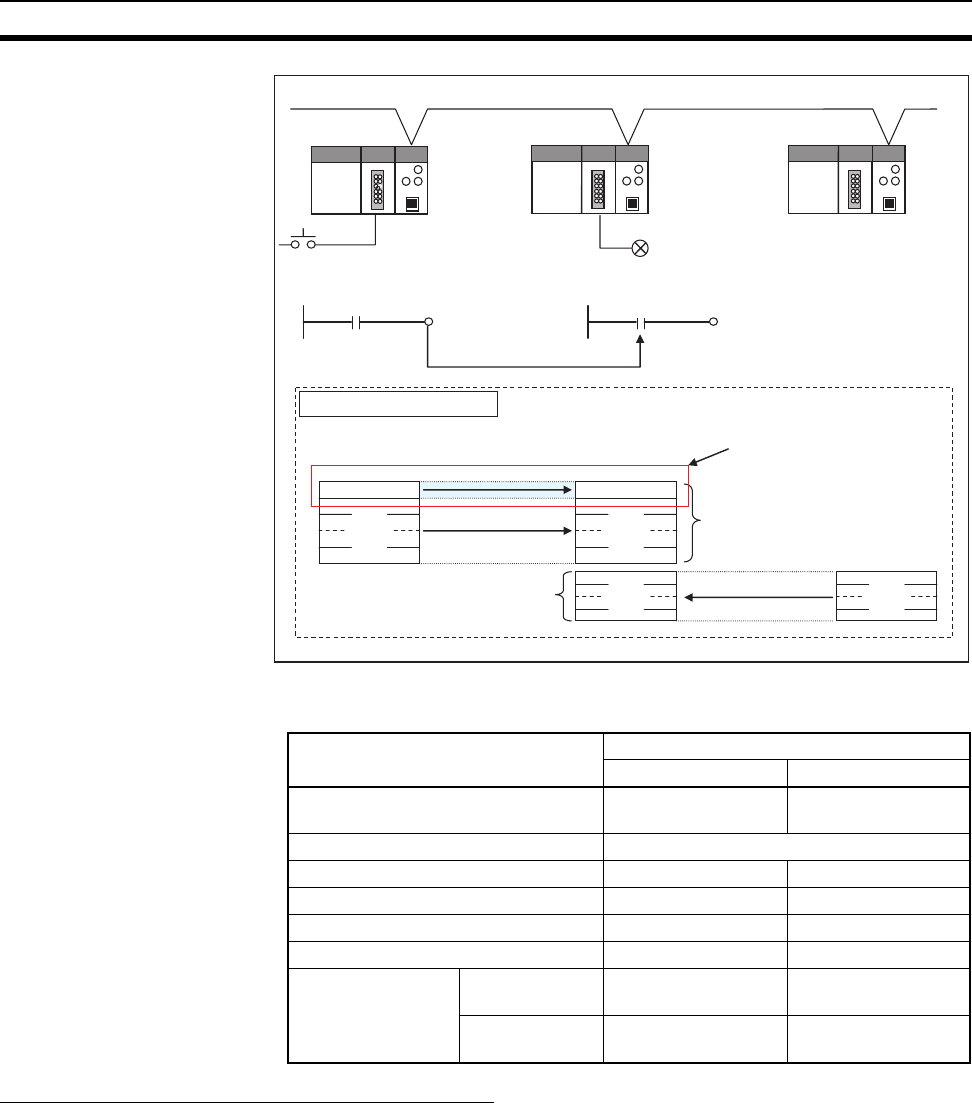
You can find the maximum I/O response time from the total of (1) to (6) in the
following figure.
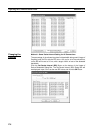
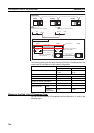
PLC#1
EtherNet/IP
PLC#2
PLC#3
Node 1
Node 2
Node 3
Input switch (external input device)
Input
W000.01
W000.01
Output
Output relay (external output device)
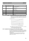
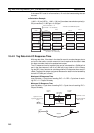
Tag Data Link Table
PLC#1
PLC#2
PLC#3
Outputs
RPI = 10 ms
RPI = 10 ms
W000
722 words x 16 connections
Total: 11,552 words
W000
Inputs
Inputs
256 words x 16 connections
Total: 4,096 words
RPI = 100 ms
Outputs
Connection 1
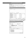
Item Value used in calculation example
PLC#1 PLC#2
External I/O device delay time Input device delay:
1.5 ms
Output device delay:
2.0 ms
Cable length 50 m
CPU Unit model CJ2H CPU Unit CJ2H CPU Unit
RPI 10 msec ---
Number of receive connections 0 32
CPU Unit cycle time 10 msec 15 msec
Total number tag
data link words
Number of send
words
11,552 None
Number of
receive words
None 15,648