


119
Overview of Tag Data Links Section 6-1
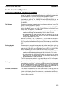
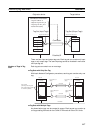
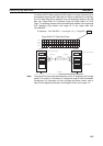
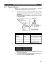
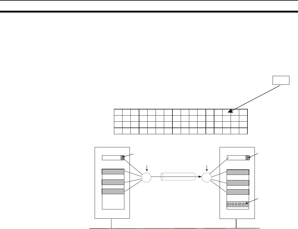
To receive the PLC status, specify the PLC status in an input (consume) tag in
the reception tag set as well. When the PLC status is specified in an input tag,
the PLC status flags will be reflected in the corresponding location in the tag
data link’s Target Node PLC Operating Flags and Target Node PLC Error
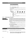
Flags. The following example shows the relationship between the Target Node
PLC Operating Flag location and target ID of the target node with
192.168.250.2.
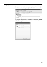
Note The target ID may be duplicated depending on the IP addresses of the target
nodes. In this case, it is necessary to change the target ID with the Network
Configurator. For information on how to change the device number, refer to
step 4 under Registering Devices in the Register Device List on page 141.
15 14 13 12 11 10 9 8 7 6 5 4 3 2 1 0
IP address = 192.168.250.2 → (Last byte = 2) → Target ID = #002
Target Node PLC Operating Flags:
n+2
n+3
n+4
n+5
15 14 13 12 11 10 9 8 7 6 5 4 3 2 1 0
31 30 29 28 27 26 25 24 23 22 21 20 19 18 17 16
47 46 45 44 43 42 41 40 39 38 37 36 35 34 33 32
63 62 61 60 59 58 57 56 55 54 53 52 51 50 49 48
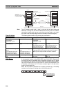
EtherNet/IP
I/O memory
CPU Unit
a
b
c
CPU Unit
f
g
h
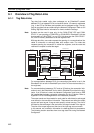
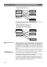
PLC status (when included)
Target data link status
PLC status
I/O memory
PLC status
Connection
Output tag set
Input tag set
PLC status (when included)