


348
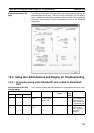
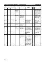
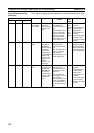
Using the LED Indicators and Display for Troubleshooting Section 14-2
Lit red Not lit H3 EtherNet/IP
Unit or built-in
EtherNet/IP
port faulty
--- Operation stops. --- Replace the Ether-
Net/IP Unit or (for a
built-in EtherNet/IP
port) the CPU Unit
if the error recurs
when the Unit is
restarted.
Flashing
red
Not lit H4 Node address
setting error
The node
address set on
the switches is
invalid (00 or
FF.)
Operation stops. --- Set the node
address correctly
and restart the Eth-
erNet/IP Unit or
built-in EtherNet/IP
port.
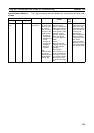
Flashing
red
Not lit H6 CPU Unit
faulty
--- Records the error in
the error log (time/
date all zeroes).
Operation stops.
000F Replace the CPU
Unit if the error
recurs when the
CPU Unit is
restarted.
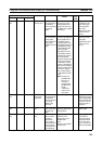
Flashing
red
Not lit H7 I/O table not
registered
The CPU Unit’s
I/O table is not
registered.
Operation stops. 0006 Create the I/O
table.
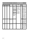
Flashing
red
--- H8 Simple backup
function
restore error
The simple
backup func-
tion’s data resto-
ration failed.
The settings of the
EtherNet/IP Unit or
built-in EtherNet/IP
port are all cleared,
unless the backup file
does not exist, a
Memory Card is not
mounted, or the PLC
model does not
match.
--- Perform the simple
backup operation
again. If the error
recurs, replace the
Memory Card, or
EtherNet/IP Unit,
or (for a built-in
EtherNet/IP port)
the CPU Unit.
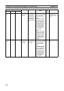
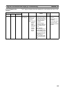
Flashing
red
--- H9 I/O bus error An error
occurred while
exchanging data
with the CPU
Unit.
• If the Unit is the orig-
inator of the tag data
link connection, it
stops communica-
tions.
• If the Unit is the tar-
get of the tag data
link connection and
the PLC status is
included in the com-
munications data,
the corresponding
Target Node PLC
Error Flag will be
turned ON.
000E Check and correct
the CPU Unit’s
operating environ-
ment.
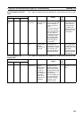
Indicator Error Cause Unit operation (Flag
status)
Error
log
(hex)
Countermeasure
MS NS 7-segment