


208
Routing Tables Section 8-4
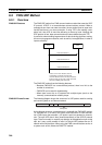
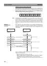
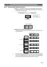
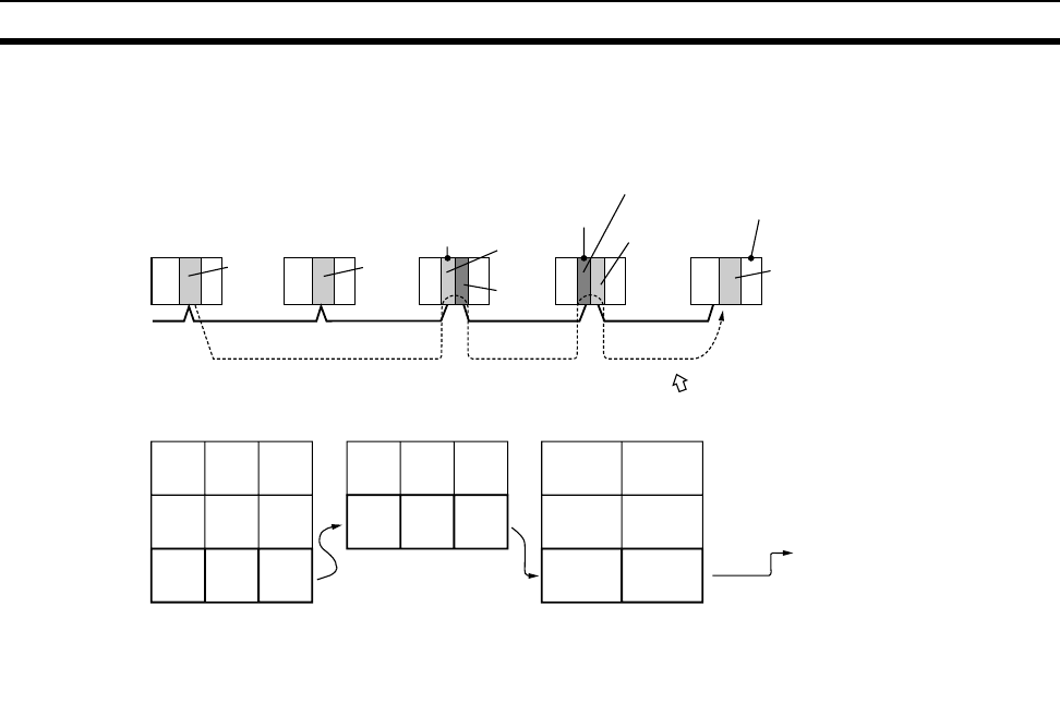
The following example shows routing tables for sending data from PLC #1 (the
local node: network address 1, node address 1) to PLC #4 (the destination
node: network address 3, node address 2).
Note In the above example, the routing tables required for a message to reach PLC
#4 from PLC #1 are shown. Additional settings would be required in the rout-
ing tables for a message to reach PLC #1 from PLC #4. Refer to 8-4-3 Rout-
ing Table Setting Examples for routing table setting examples.
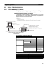
8-4-2 Connecting and Using a Peripheral Device for the PLC
Routing tables must be created by a CX-Integrator connected to the PLC.
(They cannot be created using a Programming Console.) For details on how
to connect and use the CX-Integrator, refer to the CX-Integrator Operation
Manual (W445). (CX-Integrator is automatically installed when CX-One is
installed.)
Note 1. When routing tables are transferred from the CX-Integrator to the PLC, all
of the CPU Bus Unit are reset so that the routing tables that have been cre-
ated can be read and enabled. Before transferring the routing tables, con-
firm that there will be no problems in the system when the CPU Bus Units
are reset.
2. To transfer routing tables for multiple nodes to a PLC in one batch, connect
the CX-Integrator to a PLC with only one Communications Unit mounted.
Routing tables cannot be transferred to other nodes from a PLC with mul-
tiple Communications Units mounted.
3. Routing tables can only be transferred as a batch to multiple nodes within
the same network as the PLC to which the CX-Integrator is connected.
3
2
1
3
3
1
1
20
3
3
2
2
PLC #1 (local node)
Node #1
Network #1
Node #2
PLC #2 (relay node)
PLC #3
(relay node)
Node #2
Unit #0
PLC #4 (destination node)
Node #3
Node #1
Network #2
Network #3
Node #2
Node #1
Unit #1
PLC #1
relay network table
PLC #2
relay network table
PLC #3
local network table
End network
End
network
Relay
network
Relay
node
Local
network
address
Unit
number
To go to network #3,
first go to node #3 at
network #1.
To go to network #3,
first go to node #2 at
network #2.
(To go to network #3
according to the local
network table, go
through unit
number 1 of the local
CPU Rack.)
(The network is the same,
so go to node #2 at network #3.)
End
network
Relay
network
Relay
node